
Owners Manual


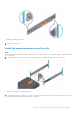

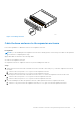

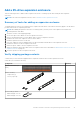

Table Of Contents
- Dell EMC PowerStore Installation and Service Guide for PowerStore 1000, 3000, 5000, 7000, and 9000 Models
- Contents
- Additional Resources
- Install a new base enclosure and optional expansion enclosure
- Install a new base enclosure
- Install a 25-drive expansion enclosure
- Summary of tasks for installing an expansion enclosure
- Verify shipping package contents
- Choose where to install the expansion enclosure
- Removing a filler panel
- Install the rails in the cabinet
- Install the expansion enclosure on the rails
- Installing drives
- Installing the front bezel
- Cable the base enclosure to the expansion enclosure
- Connect expansion enclosure power cables
- Add a 25-drive expansion enclosure
- Summary of tasks for adding an expansion enclosure
- Verify shipping package contents
- Choose where to install the expansion enclosure
- Removing a filler panel
- Install the rails in the cabinet
- Install the expansion enclosure on the rails
- Installing drives
- Installing the front bezel
- Connect expansion enclosure power cables
- Cable the base enclosure to the new expansion enclosure
- Base enclosure service procedures
- Replace a faulted drive in the base enclosure
- Add a new drive to the base enclosure
- Replace a power supply
- Replace an embedded module
- Replace a 4-port card
- Before you begin
- Identify a faulted 4-port card from PowerStore Manager
- Identify a faulted part from PowerStore Manager
- Embedded module LEDs
- Power down the node
- Remove an embedded module
- Remove a 4-port card
- Install a 4-port card
- Install an embedded module
- Power up the node
- Verify the operation of a new 4-port card
- Return a faulted part
- Replace an SFP
- Replace an I/O module
- Replace a fan module
- Before you begin
- Identify a faulted fan module from PowerStore Manager
- Power down the node
- Remove the node
- Remove the top cover from the node
- Remove the faulted fan module
- Install a new fan module
- Install the top cover on the node
- Install the node
- Power up the node
- Verify the operation of a replacement fan module
- Return a faulted part
- Replace a dual inline memory module (DIMM)
- Before you begin
- Identify a faulted DIMM from PowerStore Manager
- Power down the node
- Remove the node
- Remove the top cover from the node
- Remove the faulted dual inline memory module
- Install the dual inline memory module
- Install the top cover on the node
- Install the node
- Power up the node
- Verify the operation of a replacement DIMM
- Return a faulted part
- Replace an internal M.2 boot module
- Before you begin
- Identify a faulted internal M.2 boot module from PowerStore Manager
- Power down the node
- Remove the node
- Remove the top cover from the node
- Remove the faulted internal M.2 boot module
- Install the internal M.2 boot module
- Install the top cover on the node
- Install the node
- Power up the node
- Verify the operation of a replacement internal M.2 boot module
- Return a faulted part
- Replace an M.2 boot module adaptor
- Before you begin
- Identify a faulted M.2 boot module adaptor from PowerStore Manager
- Power down the node
- Remove the node
- Remove the top cover from the node
- Remove the faulted M.2 boot module adaptor
- Install the M.2 boot module adaptor
- Install the top cover on the node
- Install the node
- Power up the node
- Verify the operation of a replacement M.2 boot module adaptor
- Return a faulted part
- Replace a node
- Before you begin
- Identify a faulted node from PowerStore Manager
- Power down the node
- Remove the node
- Remove the top cover from the node
- Transfer parts from the faulted node to the replacement node
- Install the top cover on the node
- Install the node
- Power up the node
- Verify the operation of a replacement node
- Return a faulted part
- Expansion enclosure service procedures
- Safety precautions for handling replaceable units
- Power control procedures
- Power control procedure considerations
- Power control procedures preview
- Powering off procedures for PowerStore node
- Powering on procedures for PowerStore node
- Rebooting procedures for a PowerStore node
- Powering off procedures for PowerStore appliances
- Powering on procedures for PowerStore appliances
- Powering off procedures for PowerStore cluster
- Powering on procedures for PowerStore cluster
- Transferring the internal battery backup module
- Data collection
- Support Notifications
- Reinitialize the system

Component Quantity
Bezel for expansion
enclosure (with key)
1
Mini-SAS HD cables (1 m or
2 m copper) to loop back the
last expansion enclosure to
the node
2
Choose where to install the expansion enclosure
Before installing the new expansion enclosure, you should determine the placement of the new expansion enclosure within the
rack.
Steps
1. It is recommended that you install the expansion enclosure in the next available 2U space directly above the base enclosure
or the last expansion enclosure in the system.
Most cabinets mark 1U increments with horizontal lines or small holes in the channels.
2. Considering these recommendations, choose a 2U space in the cabinet for the expansion enclosure.
Removing a filler panel
About this task
In most cases, the front space into which you will install the enclosure is covered by a filler panel, which is attached to latch
brackets. If one or more filler panels cover the space where you want to install the enclosure, remove each panel using the
procedure that follows.
Steps
1. Remove the filler panel.
2. Use a flatblade screwdriver or similar tool to pry off the latch brackets (Prying off a latch bracket on page 20).
CL4064
Figure 12. Prying off a latch bracket
20
Install a new base enclosure and optional expansion enclosure