
Owners Manual


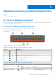


Table Of Contents
- Dell EMC PowerStore Hardware Information Guide for PowerStore 1000, 3000, 5000, 7000, and 9000
- Contents
- Additional Resources
- Platform overview
- Base enclosure component descriptions
- Expansion enclosure component descriptions
- Technical specifications
- Physical specifications for PowerStore X model and PowerStore T model
- Dimensions and weight for PowerStore X model and PowerStore T model
- Power requirements for PowerStore X model and PowerStore T model
- Power requirements for the 2U 25-drive expansion enclosure
- Operating limits
- Shipping and storage requirements

Table 9. 2U, 25-drive expansion enclosure and drive status LEDs (continued)
LED Location Color State Description
— Off Powered down
Drive fault
4
Amber On Fault
— Off No fault
Drive power and activity
5
Blue On Powering up and powered up
Blinking Drive activity
2U, 25-drive expansion enclosure rear view
The rear of the 2U, 25-drive expansion enclosure includes the following components:
● Two 12-Gb/s SAS link control cards (LCC); A (
4
) and B (
2
)
● Two power supply and cooling modules; A (
3
) and B (
1
)
B
A
0 1
#
#
0
1
x4x4
x4
x4
1
2
3
4
Figure 11. 2U, 25-drive expansion enclosure rear component locations
2U, 25-drive expansion enclosure link control card
Link control card functions and features
The link control card (LCC) supports, controls, and monitors the expansion enclosure, and is the primary interconnect
management element. Each LCC includes connectors for input and output to downstream devices.
The LCCs in an expansion enclosure connects to the node and other expansion enclosures. The cables connect the LCCs in a
system in a daisy-chain topology.
Internally, each expansion enclosure LCC uses protocols to emulate a loop. The LCC connects to the drives in its enclosure in a
point-to-point fashion through an internal switch. The LCC independently receives and electrically terminates incoming signals.
For traffic from the node, the LCC switch passes the signal from the input port to the drive being accessed. The switch then
forwards the drive output signal to the port.
Each LCC independently monitors the environmental status of the entire enclosure, using a microcomputer-controlled monitor
program. The monitor communicates the status to the storage processor, which polls expansion enclosure status. LCC firmware
also controls the SAS and drive-module status LEDs.
Each LCC includes an enclosure ID display.
12-Gb/s LCC ports, LEDs, and connectors
Each 2U, 25 expansion enclosure LCC shows the following ports, LEDs, and connectors:
16
Expansion enclosure component descriptions