
Owners Manual


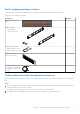


Table Of Contents
- Dell EMC PowerStore Installation and Service Guide for PowerStore 1000, 3000, 5000, 7000, and 9000 Models
- Contents
- Additional Resources
- Install a new base enclosure and optional expansion enclosure
- Install a new base enclosure
- Install a 25-drive expansion enclosure
- Summary of tasks for installing an expansion enclosure
- Verify shipping package contents
- Choose where to install the expansion enclosure
- Removing a filler panel
- Install the rails in the cabinet
- Install the expansion enclosure on the rails
- Installing drives
- Installing the front bezel
- Cable the base enclosure to the expansion enclosure
- Connect expansion enclosure power cables
- Verify the operation of the new part
- Add a 25-drive expansion enclosure
- Summary of tasks for adding an expansion enclosure
- Verify shipping package contents
- Choose where to install the expansion enclosure
- Removing a filler panel
- Install the rails in the cabinet
- Install the expansion enclosure on the rails
- Installing drives
- Installing the front bezel
- Connect expansion enclosure power cables
- Cable the base enclosure to the new expansion enclosure
- Verify the operation of the new part
- Base enclosure service procedures
- Replace a faulted drive in the base enclosure
- Add a new drive to the base enclosure
- Replace a power supply
- Replace an embedded module
- Replace a 4-port card
- Replace an SFP
- Replace an I/O module
- Replace a fan module
- Replace a dual inline memory module (DIMM)
- Identify a faulted part from PowerStore Manager
- Power down the node
- Remove the node
- Remove the top cover from the node
- Remove the faulted dual inline memory module
- Install the dual inline memory module
- Install the top cover on the node
- Install the node
- Power up the node
- Verify the operation of a replacement part
- Return a faulted part
- Replace an internal M.2 boot module
- Identify a faulted part from PowerStore Manager
- Power down the node
- Remove the node
- Remove the top cover from the node
- Remove the faulted internal M.2 boot module
- Install the internal M.2 boot module
- Install the top cover on the node
- Install the node
- Power up the node
- Verify the operation of a replacement part
- Return a faulted part
- Replace an M.2 boot module adaptor
- Identify a faulted part from PowerStore Manager
- Power down the node
- Remove the node
- Remove the top cover from the node
- Remove the faulted M.2 boot module adaptor
- Install the M.2 boot module adaptor
- Install the top cover on the node
- Install the node
- Power up the node
- Verify the operation of a replacement part
- Return a faulted part
- Replace a node
- Identify a faulted part from PowerStore Manager
- Power down the node
- Remove the node
- Remove the top cover from the node
- Transfer parts from the faulted node to the replacement node
- Transfer the internal battery backup module
- Install the top cover on the node
- Install the node
- Power up the node
- Verify the operation of a replacement part
- Return a faulted part
- Expansion enclosure service procedures
- Safety precautions for handling replaceable units
- Discovering PowerStore Appliances
- Power control procedures
- Power control procedure considerations
- Power control procedures preview
- Powering off procedures for PowerStore node
- Powering on procedures for PowerStore node
- Rebooting procedures for a PowerStore node
- Powering off procedures for PowerStore appliances
- Powering on procedures for PowerStore appliances
- Powering off procedures for PowerStore cluster
- Powering on procedures for PowerStore cluster
- Data collection
- Support Notifications
- Reinitialize the system

Verify the operation of the new part
Steps
1. From PowerStore Manager, select Hardware.
2. Select the appliance where you installed the new part.
3. From the Hardware card, select the view of the system where the part was installed.
The status of the part should read Healthy. If the status is Faulted, wait a few minutes and refresh PowerStore
Manager. If the status does not change, ensure the part is correctly seated, or call support.
Add a 25-drive expansion enclosure
Take the following actions to add a 25-drive expansion enclosure to a running system with existing 25-drive expansion
enclosures.
NOTE: If this is the first expansion enclosure, refer to Install a 25-drive expansion enclosure.
Summary of tasks for adding an expansion enclosure
To add an expansion enclosure to a running system, complete the tasks below in the order in which they appear. This document
provides instructions for completing each task.
NOTE:
When adding an expansion enclosure to a running system, you must power on the expansion enclosure before
attaching the back-end cables.
1. Verify the contents of the shipping package.
2. Choose the space in the cabinet for the new expansion enclosure.
3. Remove the filler panels that cover the cabinet space for the new expansion enclosure.
4. Install the rails for the new expansion enclosure in the cabinet.
5. Install the expansion enclosure on the rails.
6. If the new expansion enclosure shipped without its drives installed, install the drives in the expansion enclosure.
7. Install the front bezel on the new expansion enclosure.
8. Attach the power cables to the new expansion enclosure.
9. Attach the expansion (back-end) cables to the new expansion enclosure as described in Cable the base enclosure to the new
expansion enclosure on page 24.
10. Verify the operation of the new expansion enclosure.
Verify shipping package contents
Confirm that you received all the equipment that is required to install the new 25-drive expansion enclosure.
Verify that you received the following:
Component
Quantity
Expansion enclosure (25-
drive)
1
Install a new base enclosure and optional expansion enclosure 19