
Owners Manual


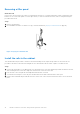


Table Of Contents
- Dell EMC PowerStore Installation and Service Guide for PowerStore 1000, 3000, 5000, 7000, and 9000 Models
- Contents
- Additional Resources
- Install a new base enclosure and optional expansion enclosure
- Install a new base enclosure
- Install a 25-drive expansion enclosure
- Summary of tasks for installing an expansion enclosure
- Verify shipping package contents
- Choose where to install the expansion enclosure
- Removing a filler panel
- Install the rails in the cabinet
- Install the expansion enclosure on the rails
- Installing drives
- Installing the front bezel
- Cable the base enclosure to the expansion enclosure
- Connect expansion enclosure power cables
- Verify the operation of the new part
- Add a 25-drive expansion enclosure
- Summary of tasks for adding an expansion enclosure
- Verify shipping package contents
- Choose where to install the expansion enclosure
- Removing a filler panel
- Install the rails in the cabinet
- Install the expansion enclosure on the rails
- Installing drives
- Installing the front bezel
- Connect expansion enclosure power cables
- Cable the base enclosure to the new expansion enclosure
- Verify the operation of the new part
- Base enclosure service procedures
- Replace a faulted drive in the base enclosure
- Add a new drive to the base enclosure
- Replace a power supply
- Replace an embedded module
- Replace a 4-port card
- Replace an SFP
- Replace an I/O module
- Replace a fan module
- Replace a dual inline memory module (DIMM)
- Identify a faulted part from PowerStore Manager
- Power down the node
- Remove the node
- Remove the top cover from the node
- Remove the faulted dual inline memory module
- Install the dual inline memory module
- Install the top cover on the node
- Install the node
- Power up the node
- Verify the operation of a replacement part
- Return a faulted part
- Replace an internal M.2 boot module
- Identify a faulted part from PowerStore Manager
- Power down the node
- Remove the node
- Remove the top cover from the node
- Remove the faulted internal M.2 boot module
- Install the internal M.2 boot module
- Install the top cover on the node
- Install the node
- Power up the node
- Verify the operation of a replacement part
- Return a faulted part
- Replace an M.2 boot module adaptor
- Identify a faulted part from PowerStore Manager
- Power down the node
- Remove the node
- Remove the top cover from the node
- Remove the faulted M.2 boot module adaptor
- Install the M.2 boot module adaptor
- Install the top cover on the node
- Install the node
- Power up the node
- Verify the operation of a replacement part
- Return a faulted part
- Replace a node
- Identify a faulted part from PowerStore Manager
- Power down the node
- Remove the node
- Remove the top cover from the node
- Transfer parts from the faulted node to the replacement node
- Transfer the internal battery backup module
- Install the top cover on the node
- Install the node
- Power up the node
- Verify the operation of a replacement part
- Return a faulted part
- Expansion enclosure service procedures
- Safety precautions for handling replaceable units
- Discovering PowerStore Appliances
- Power control procedures
- Power control procedure considerations
- Power control procedures preview
- Powering off procedures for PowerStore node
- Powering on procedures for PowerStore node
- Rebooting procedures for a PowerStore node
- Powering off procedures for PowerStore appliances
- Powering on procedures for PowerStore appliances
- Powering off procedures for PowerStore cluster
- Powering on procedures for PowerStore cluster
- Data collection
- Support Notifications
- Reinitialize the system

Removing a filler panel
About this task
In most cases, the front space into which you will install the enclosure is covered by a filler panel, which is attached to latch
brackets. If one or more filler panels cover the space where you want to install the enclosure, remove each panel using the
procedure that follows.
Steps
1. Remove the filler panel.
2. Use a flatblade screwdriver or similar tool to pry off the latch brackets (Prying off a latch bracket on page 14).
CL4064
Figure 5. Prying off a latch bracket
Install the rails in the cabinet
This task describes the procedure to install one rail. After installing one rail, repeat the procedure for the other rail. The
procedure is the same for both the left and right rail. You can install the rails into either a square or round hole rack.
Steps
1. Position the rail end piece so the label FRONT is located at the front of the rack and facing towards the inside of the rack,
while orienting the rear of the rail to align level with the holes on the rear of the rack.
2. From the rear of the rack, pull the rail straight back until the latch is locked.
3. To install the front end piece of the rail, press the blue latch release button until the latch rotates open.
4. Pull the rail forward until the pins slide into the holes on the front of the rack, then release the latch to secure the rail in
place.
14
Install a new base enclosure and optional expansion enclosure