
Specifications


Dell
PowerEdge T710 Technical Guide 19
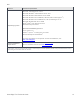
Power Off Security
The control panel is designed so the power switch cannot be accidentally
activated. The lock on the bezel secures the switch behind the bezel. In
addition, there is a setting in the CMOS setup that disables the power button
function.
Intrusion Alert
A switch mounted on the inside of the chassis on the cooling shroud, is used
to detect chassis intrusion. When the cover is opened, the switch circuit
closes to indicate intrusion.
Secure Mode
BIOS has the ability to enter a secure boot mode through Setup. This mode
includes the option to lock out the power and NMI switches on the control
panel or set up a system password. For more information, see System and
Setup Password Features section in the About Your System chapter in the
PowerEdge T710 Hardware Owner’s Manual on Support.Dell.com.
4.11.1 USB Key
The port on the motherboard is for an optional USB key and is located inside the chassis. Some
possible applications of the USB key are listed as follows:
User custom boot and pre-boot OS for ease of deployment or diskless environments
USB license keys for software applications like eToken™ or Sentinel Hardware Keys
Storage of custom logs or scratch pads for portable user defined information (not hot-
pluggable)
4.12 Battery
A replaceable coin cell CR2032 3V battery is mounted on the planar to provide backup power for the
Real-Time Clock and CMOS RAM on the ICH chip.
4.13 Field Replaceable Units (FRU)
The planar contains a serial EEPROM to store FRU information including Dell part number, part
revision level, and serial number. The backplane storage enclosure processor (SEP) and the power
supply microcontroller are also used to store FRU data.
4.14 User Accessible Jumpers, Sockets, and Connectors
See the Jumpers and Connectors chapter in the PowerEdge T710 Hardware Owner’s Manual on
Support.Dell.com.