
Owners Manual


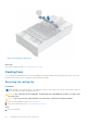


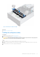

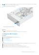

Table Of Contents
- Dell EMC PowerEdge R940xa Installation and Service Manual
- About this document
- PowerEdge R940xa system overview
- Initial system setup and configuration
- Installing and removing system components
- Safety instructions
- Before working inside your system
- After working inside your system
- Recommended tools
- Front bezel
- Drives
- System cover
- Support bar
- Cooling fans
- Cooling fan assembly
- Optional USB 3.0 module
- Optional optical drive
- Control panel
- Air shroud
- NVDIMM-N battery
- Drive backplane
- System memory
- Processors and heat sinks
- Expansion cards and expansion card risers
- Expansion card installation guidelines
- Removing the expansion card riser
- Installing the expansion card riser
- Removing the expansion card from the riser
- Installing the expansion card in the riser
- Removing the expansion card from the system board
- Installing the expansion card on the system board
- GPU card installation guidelines
- Removing the GPU
- Installing the GPU
- M.2 SSD module
- Optional IDSDM or vFlash module
- Network daughter card
- System battery
- Optional internal USB memory key
- Power supply units
- Power interposer board
- Trusted Platform Module
- System board
- Jumpers and connectors
- System diagnostics and indicator codes
- Getting help
- Documentation resources

Figure 29. Removing the support bar
Next steps
1. Replace the support bar.
Installing the support bar
Prerequisites
1. Follow the safety guidelines listed in Safety instructions.
2. Follow the procedure listed in Before working inside your system.
Steps
1. Align the support bar slots with the tabs on the system chassis.
2. Pull the blue release pins and lower the support bar into the system until it locks in place.
3. Tighten the thumb screws to secure the support with the chassis.
Installing and removing system components
33