
Owners Manual


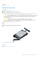


Table Of Contents
- Dell EMC PowerEdge R940xa Installation and Service Manual
- About this document
- PowerEdge R940xa system overview
- Initial system setup and configuration
- Installing and removing system components
- Safety instructions
- Before working inside your system
- After working inside your system
- Recommended tools
- Front bezel
- Drives
- System cover
- Support bar
- Cooling fans
- Cooling fan assembly
- Optional USB 3.0 module
- Optional optical drive
- Control panel
- Air shroud
- NVDIMM-N battery
- Drive backplane
- System memory
- Processors and heat sinks
- Expansion cards and expansion card risers
- Expansion card installation guidelines
- Removing the expansion card riser
- Installing the expansion card riser
- Removing the expansion card from the riser
- Installing the expansion card in the riser
- Removing the expansion card from the system board
- Installing the expansion card on the system board
- GPU card installation guidelines
- Removing the GPU
- Installing the GPU
- M.2 SSD module
- Optional IDSDM or vFlash module
- Network daughter card
- System battery
- Optional internal USB memory key
- Power supply units
- Power interposer board
- Trusted Platform Module
- System board
- Jumpers and connectors
- System diagnostics and indicator codes
- Getting help
- Documentation resources

Installing and removing system components
CAUTION: Many repairs may only be done by a certified service technician. You should only perform
troubleshooting and simple repairs as authorized in your product documentation, or as directed by the online or
telephone service and support team. Damage due to servicing that is not authorized by Dell is not covered by
your warranty. Read and follow the safety instructions that are shipped with your product.
Topics:
• Safety instructions
• Before working inside your system
• After working inside your system
• Recommended tools
• Front bezel
• Drives
• System cover
• Support bar
• Cooling fans
• Cooling fan assembly
• Optional USB 3.0 module
• Optional optical drive
• Control panel
• Air shroud
• NVDIMM-N battery
• Drive backplane
• System memory
• Processors and heat sinks
• Expansion cards and expansion card risers
• M.2 SSD module
• Optional IDSDM or vFlash module
• Network daughter card
• System battery
• Optional internal USB memory key
• Power supply units
• Power interposer board
• Trusted Platform Module
•
System board
Safety instructions
NOTE:
Whenever you need to lift the system, get others to assist you. To avoid injury, do not attempt to lift the system by
yourself.
WARNING: Opening or removing the system cover while the system is powered on may expose you to a risk of
electric shock.
CAUTION: Do not operate the system without the cover for a duration exceeding five minutes. Operating the
system without the system cover can result in component damage.
CAUTION: Many repairs may only be done by a certified service technician. You should only perform
troubleshooting and simple repairs as authorized in your product documentation, or as directed by the online or
4
22 Installing and removing system components