
Owners Manual

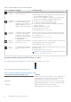


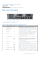


Table Of Contents
- Dell EMC PowerEdge R740xd Installation and Service Manual
- Contents
- PowerEdge R740xd system overview
- Documentation resources
- Initial system setup and configuration
- Installing and removing system components
- Safety instructions
- Before working inside your system
- After working inside your system
- Recommended tools
- Optional front bezel
- System cover
- Backplane cover
- Inside the system
- Air shroud
- Cooling fan assembly
- Cooling fans
- Intrusion switch
- NVDIMM-N battery
- Mid drive tray
- Mid drive tray details
- Removing mid drive tray
- Installing the mid drive tray
- Removing drive blank from drive carrier
- Installing drive blank into the drive carrier
- Removing drive carrier from the mid drive tray
- Installing drive carrier into mid drive tray
- Removing 3.5 inch drive from the drive carrier
- Installing 3.5 inch drive into the drive carrier
- Removing a 2.5 inch drive from the 3.5 inch mid drive carrier
- Installing a 2.5 inch drive into the 3.5 inch mid drive carrier
- Drives
- Drive guidelines
- Removing a drive blank
- Installing a drive blank
- Removing a drive carrier
- Installing a drive carrier
- Removing a 2.5 inch drive from the 3.5 inch drive adapter
- Installing a 2.5 inch drive into the 3.5 inch drive adapter
- Removing a 3.5 inch adapter from a 3.5 inch drive carrier
- Installing a 3.5 inch adapter into a 3.5 inch drive carrier
- Removing the drive from the drive carrier
- Installing a drive into the drive carrier
- Rear drive cage
- System memory
- Processors and heat sinks
- Expansion cards and expansion card risers
- Expansion card installation guidelines
- Opening and closing the PCIe card holder latch
- Removing expansion card from the expansion card riser
- Installing expansion card into the expansion card riser
- Removing riser 2 and 3 blank
- Installing riser 2 and 3 blank
- Removing riser 3 blank
- Installing riser 3 blank
- Removing expansion card riser 1
- Installing expansion card riser 1
- Removing expansion card riser 2
- Installing expansion card riser 2
- Removing expansion card riser 3
- Installing expansion card riser 3
- GPU or ACLR card installation guidelines
- Removing a GPU
- Installing a GPU
- M.2 SSD module
- Optional MicroSD or vFlash card
- Optional IDSDM or vFlash module
- Network daughter card
- Integrated storage controller card
- Backplane
- Backplane details
- Removing the backplane
- Installing the backplane
- Removing mid drive tray backplane
- Installing mid drive tray backplane
- Removing the 3.5 inch drive rear backplane
- Installing the 3.5 inch drive rear backplane
- Removing the 2.5 inch drive rear backplane
- Installing the 2.5 inch drive rear backplane
- Cable routing
- System battery
- Optional internal USB memory key
- Power supply units
- System board
- Trusted Platform Module
- Control panel
- System diagnostics
- Jumpers and connectors
- Getting help

Table 10. Features available on the back view of 2 x 3.5 inch drive system (continued)
Item Panels, ports and slots Icon Description
button to reset iDRAC and to access BIOS using the step through
mode.
NOTE: For more information, see the Dell EMC PowerEdge R740xd Technical Specifications on the product documentation
page.
NIC indicator codes
Each NIC on the back of the system has indicators that provide information about the activity and link status. The activity LED
indicator indicates if data is flowing through the NIC, and the link LED indicator indicates the speed of the connected network.
Figure 10. NIC indicator codes
1. link LED indicator
2. activity LED indicator
Table 11. NIC indicator codes
Status Condition
Link and activity indicators are off The NIC is not connected to the network.
Link indicator is green and activity indicator is blinking
green
The NIC is connected to a valid network at its maximum port speed
and data is being sent or received.
Link indicator is amber and activity indicator is blinking
green
The NIC is connected to a valid network at less than its maximum
port speed and data is being sent or received.
Link indicator is green and activity indicator is off The NIC is connected to a valid network at its maximum port speed
and data is not being sent or received.
Link indicator is amber and activity indicator is off The NIC is connected to a valid network at less than its maximum
port speed and data is not being sent or received.
Link indicator is blinking green and activity is off NIC identify is enabled through the NIC configuration utility.
Power supply unit indicator codes
AC power supply units (PSUs) have an illuminated translucent handle that serves as an indicator.
The DC PSUs have an LED that serves as an indicator.
The indicator shows whether power is present or if a power fault has occurred.
PowerEdge R740xd system overview
17