
Owners Manual
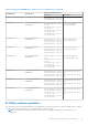


Table Of Contents
- Dell EMC PowerEdge R740xd Installation and Service Manual
- PowerEdge R740xd system overview
- Documentation resources
- Initial system setup and configuration
- Installing and removing system components
- Safety instructions
- Before working inside your system
- After working inside your system
- Recommended tools
- Optional front bezel
- System cover
- Backplane cover
- Inside the system
- Air shroud
- Cooling fan assembly
- Cooling fans
- Intrusion switch
- NVDIMM-N battery
- Mid drive tray
- Mid drive tray details
- Removing mid drive tray
- Installing the mid drive tray
- Removing drive blank from drive carrier
- Installing drive blank into the drive carrier
- Removing drive carrier from the mid drive tray
- Installing drive carrier into mid drive tray
- Removing 3.5 inch drive from the drive carrier
- Installing 3.5 inch drive into the drive carrier
- Removing a 2.5 inch drive from the 3.5 inch mid drive carrier
- Installing a 2.5 inch drive into the 3.5 inch mid drive carrier
- Drives
- Drive guidelines
- Removing a drive blank
- Installing a drive blank
- Removing a drive carrier
- Installing a drive carrier
- Removing a 2.5 inch drive from the 3.5 inch drive adapter
- Installing a 2.5 inch drive into the 3.5 inch drive adapter
- Removing a 3.5 inch adapter from a 3.5 inch drive carrier
- Installing a 3.5 inch adapter into a 3.5 inch drive carrier
- Removing the drive from the drive carrier
- Installing a drive into the drive carrier
- Rear drive cage
- System memory
- Processors and heat sinks
- Expansion cards and expansion card risers
- Expansion card installation guidelines
- Opening and closing the PCIe card holder latch
- Removing expansion card from the expansion card riser
- Installing expansion card into the expansion card riser
- Removing riser 2 and 3 blank
- Installing riser 2 and 3 blank
- Removing riser 3 blank
- Installing riser 3 blank
- Removing expansion card riser 1
- Installing expansion card riser 1
- Removing expansion card riser 2
- Installing expansion card riser 2
- Removing expansion card riser 3
- Installing expansion card riser 3
- GPU card installation guidelines
- Removing a GPU
- Installing a GPU
- M.2 SSD module
- Optional MicroSD or vFlash card
- Optional IDSDM or vFlash module
- Network daughter card
- Integrated storage controller card
- Backplane
- Backplane details
- Removing the backplane
- Installing the backplane
- Removing mid drive tray backplane
- Installing mid drive tray backplane
- Removing the 3.5 inch drive rear backplane
- Installing the 3.5 inch drive rear backplane
- Removing the 2.5 inch drive rear backplane
- Installing the 2.5 inch drive rear backplane
- Cable routing
- System battery
- Optional internal USB memory key
- Power supply units
- System board
- Trusted Platform Module
- Control panel
- System diagnostics
- Jumpers and connectors
- Getting help

Table 23. 4 socket DCPMM configurations (continued)
No. of
CPUs in
the
Server
DCPMM
Populat
ion
DRAM
Populat
ion
DRAM
Capacit
y (GB)
DCPMM
Capacit
y (GB)
Operati
ng
system
Memory
in
Memory
Mode
(GB)
Total
Memory
(GB)
Total
Memory
per
CPU
(GB)
Ratio
DRAM
to
Optane
Memory
Require
s an M
or L
CPU
Support
ed in
App
Direct
Mode
Support
ed in
Memory
Mode
4 512 GB x
16
64 GB x
24
1,536 8,192 8,192 9,728 2,432 1 : 5.3 L SKU Yes Yes
4 512 GB x
24
64 GB x
24
1,536 12,288 12,288 13,824 3,456 1 : 8 L SKU Yes Yes
4 512 GB x
24
128 GB x
24
3,072 12,288 12,288 15,360 3,840 1 : 4 L SKU Yes Yes
4 256 GB
x 16
16 GB x
24
384 4,096 4,096 4,480 1,120 1 : 10.7 L SKU Yes Yes
4 256 GB
x 24
16 GB x
24
384 6,144 6,144 6,528 1,632 1 : 16 L SKU Yes Yes
4 256 GB
x 16
32 GB x
24
768 4,096 4,096 4,864 1,216 1 : 5.3 L SKU Yes Yes
4 256 GB
x 24
32 GB x
24
768 6,144 6,144 6,912 1,728 1 : 8 L SKU Yes Yes
4 256 GB
x 16
64 GB x
24
1,536 4,096 N/A 5,632 1,408 1 : 2.7 L SKU Yes No
4 256 GB
x 24
64 GB x
24
1,536 6,144 6,144 7,680 1,920 1 : 4 L SKU Yes Yes
4 256 GB
x 24
128 GB x
24
3,072 6,144 N/A 9,216 2,304 1 : 2 L SKU Yes No
NOTE: There are limited configurations available for Dual Socket Servers with only one CPU populated.
NOTE: DCPMM is supported on systems with 1600W and 2400W PSU configuration.
NOTE:
● High Performance Fan is required with DCPMM.
● GPU and FGPA cards are not supported.
● Mid or rear storage is not supported.
● Front 12 x 3.5-inch drives are not supported.
Mode-specific guidelines
The configurations allowed depend on the memory mode selected in the System BIOS.
Table 24. Memory operating modes
Memory Operating Mode Description
Optimizer Mode The Optimizer Mode if enabled, the DRAM controllers
operate independently in the 64-bit mode and provide
optimized memory performance.
NOTE: DCPMM supports only Optimizer mode.
Mirror Mode The Mirror Mode if enabled, the system maintains two
identical copies of data in memory, and the total available
84 Installing and removing system components