
Owners Manual


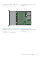


Table Of Contents
- Dell EMC PowerEdge R740xd Installation and Service Manual
- PowerEdge R740xd system overview
- Documentation resources
- Initial system setup and configuration
- Installing and removing system components
- Safety instructions
- Before working inside your system
- After working inside your system
- Recommended tools
- Optional front bezel
- System cover
- Backplane cover
- Inside the system
- Air shroud
- Cooling fan assembly
- Cooling fans
- Intrusion switch
- NVDIMM-N battery
- Mid drive tray
- Mid drive tray details
- Removing mid drive tray
- Installing the mid drive tray
- Removing drive blank from drive carrier
- Installing drive blank into the drive carrier
- Removing drive carrier from the mid drive tray
- Installing drive carrier into mid drive tray
- Removing 3.5 inch drive from the drive carrier
- Installing 3.5 inch drive into the drive carrier
- Removing a 2.5 inch drive from the 3.5 inch mid drive carrier
- Installing a 2.5 inch drive into the 3.5 inch mid drive carrier
- Drives
- Drive guidelines
- Removing a drive blank
- Installing a drive blank
- Removing a drive carrier
- Installing a drive carrier
- Removing a 2.5 inch drive from the 3.5 inch drive adapter
- Installing a 2.5 inch drive into the 3.5 inch drive adapter
- Removing a 3.5 inch adapter from a 3.5 inch drive carrier
- Installing a 3.5 inch adapter into a 3.5 inch drive carrier
- Removing the drive from the drive carrier
- Installing a drive into the drive carrier
- Rear drive cage
- System memory
- Processors and heat sinks
- Expansion cards and expansion card risers
- Expansion card installation guidelines
- Opening and closing the PCIe card holder latch
- Removing expansion card from the expansion card riser
- Installing expansion card into the expansion card riser
- Removing riser 2 and 3 blank
- Installing riser 2 and 3 blank
- Removing riser 3 blank
- Installing riser 3 blank
- Removing expansion card riser 1
- Installing expansion card riser 1
- Removing expansion card riser 2
- Installing expansion card riser 2
- Removing expansion card riser 3
- Installing expansion card riser 3
- GPU card installation guidelines
- Removing a GPU
- Installing a GPU
- M.2 SSD module
- Optional MicroSD or vFlash card
- Optional IDSDM or vFlash module
- Network daughter card
- Integrated storage controller card
- Backplane
- Backplane details
- Removing the backplane
- Installing the backplane
- Removing mid drive tray backplane
- Installing mid drive tray backplane
- Removing the 3.5 inch drive rear backplane
- Installing the 3.5 inch drive rear backplane
- Removing the 2.5 inch drive rear backplane
- Installing the 2.5 inch drive rear backplane
- Cable routing
- System battery
- Optional internal USB memory key
- Power supply units
- System board
- Trusted Platform Module
- Control panel
- System diagnostics
- Jumpers and connectors
- Getting help

Steps
Slide the PSU into the system until the PSU is fully seated and the release latch snaps into place.
Figure 159. Installing a power supply unit
Next steps
1. If you have unlatched the cable management arm, relatch it. For information about the cable management arm, see the
system’s rack documentation at www.dell.com/poweredgemanuals.
2. Connect the power cable to the PSU, and plug the cable into a power outlet.
CAUTION: When connecting the power cable to the PSU, secure the cable to the PSU with the strap.
NOTE: When installing, hot swapping, or hot adding a new PSU, wait for 15 seconds for the system to recognize the
PSU and determine its status. The PSU redundancy may not occur until discovery is complete. Wait until the new PSU is
discovered and enabled before you remove the other PSU. The PSU status indicator turns green to signify that the PSU
is functioning properly.
Wiring instructions for a DC power supply unit
Your system supports up to two –(48–60) V DC power supply units (PSUs).
NOTE:
For equipment using –(48–60) V DC power supply units (PSUs), a qualified electrician must perform all connections
to DC power and to safety grounds. Do not attempt connecting to DC power or installing grounds yourself. All electrical
wiring must comply with applicable local or national codes and practices. Damage due to servicing that is not authorized by
Dell is not covered by your warranty. Read and follow all safety instructions that came with the product.
CAUTION: Wire the unit with copper only, unless otherwise specified, use only 10 American Wire Gauge (AWG)
wire rated minimum 90ºC for source and return. Protect the –(48–60) V DC (1 wire) with a branch circuit
over-current protection rated 50 A for DC with a high interrupt current rating.
CAUTION: Connect the equipment to a –(48–60) V DC supply source that is electrically isolated from the AC
source (reliably grounded –(48–60) V DC SELV source). Ensure that the –(48–60) V DC source is efficiently
secured to earth (ground).
NOTE: A readily accessible disconnect device that is suitably approved and rated shall be incorporated in the field wiring.
Installing and removing system components 159