
Owners Manual


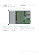


Table Of Contents
- Dell EMC PowerEdge R740xd Installation and Service Manual
- PowerEdge R740xd system overview
- Documentation resources
- Initial system setup and configuration
- Installing and removing system components
- Safety instructions
- Before working inside your system
- After working inside your system
- Recommended tools
- Optional front bezel
- System cover
- Backplane cover
- Inside the system
- Air shroud
- Cooling fan assembly
- Cooling fans
- Intrusion switch
- NVDIMM-N battery
- Mid drive tray
- Mid drive tray details
- Removing mid drive tray
- Installing the mid drive tray
- Removing drive blank from drive carrier
- Installing drive blank into the drive carrier
- Removing drive carrier from the mid drive tray
- Installing drive carrier into mid drive tray
- Removing 3.5 inch drive from the drive carrier
- Installing 3.5 inch drive into the drive carrier
- Removing a 2.5 inch drive from the 3.5 inch mid drive carrier
- Installing a 2.5 inch drive into the 3.5 inch mid drive carrier
- Drives
- Drive guidelines
- Removing a drive blank
- Installing a drive blank
- Removing a drive carrier
- Installing a drive carrier
- Removing a 2.5 inch drive from the 3.5 inch drive adapter
- Installing a 2.5 inch drive into the 3.5 inch drive adapter
- Removing a 3.5 inch adapter from a 3.5 inch drive carrier
- Installing a 3.5 inch adapter into a 3.5 inch drive carrier
- Removing the drive from the drive carrier
- Installing a drive into the drive carrier
- Rear drive cage
- System memory
- Processors and heat sinks
- Expansion cards and expansion card risers
- Expansion card installation guidelines
- Opening and closing the PCIe card holder latch
- Removing expansion card from the expansion card riser
- Installing expansion card into the expansion card riser
- Removing riser 2 and 3 blank
- Installing riser 2 and 3 blank
- Removing riser 3 blank
- Installing riser 3 blank
- Removing expansion card riser 1
- Installing expansion card riser 1
- Removing expansion card riser 2
- Installing expansion card riser 2
- Removing expansion card riser 3
- Installing expansion card riser 3
- GPU card installation guidelines
- Removing a GPU
- Installing a GPU
- M.2 SSD module
- Optional MicroSD or vFlash card
- Optional IDSDM or vFlash module
- Network daughter card
- Integrated storage controller card
- Backplane
- Backplane details
- Removing the backplane
- Installing the backplane
- Removing mid drive tray backplane
- Installing mid drive tray backplane
- Removing the 3.5 inch drive rear backplane
- Installing the 3.5 inch drive rear backplane
- Removing the 2.5 inch drive rear backplane
- Installing the 2.5 inch drive rear backplane
- Cable routing
- System battery
- Optional internal USB memory key
- Power supply units
- System board
- Trusted Platform Module
- Control panel
- System diagnostics
- Jumpers and connectors
- Getting help

Figure 153. Cable routing - 12x3.5-inch Hybrid backplane with NVMe U.2 SSD
1.
drive backplane 2. backplane signal cable (BP:BP_SIG1 to MB: BP_SIG1)
3. backplane power cable 4. SAS cable (BP:BP_SAS_A1 to RAID controller [H330] at
riser slot 3) - connects to drive 0, 1, 2, 3
5. SAS cable (BP:BP_SAS_B1 to RAID controller [H330] at
riser slot 3) - connects to drive 4, 5, 6, 7
6. SAS cable ( Rear backplane to RAID controller [H740P] at
riser slot 2)
7. Rear drive backplane 8. PCIe HOST card at riser slot 1
9. RAID controller [H740P] at riser slot 2 10. RAID controller [H330] at riser slot 3
11. PCIe cable (BP:BP_PCIe_B to HOST card at riser slot 1) -
NVMe drive 10,11
12. PCIe cable (BP:BP_PCIe_A to HOST card at riser slot 1) -
NVMe drive 8,9
System battery
Replacing the system battery
Prerequisites
WARNING:
There is a danger of a new battery exploding if it is incorrectly installed. Replace the battery only
with the same or equivalent type recommended by the manufacturer. For more information, see the safety
information that shipped with your system.
1. Follow the safety guidelines listed in Safety instructions.
2. Follow the procedure listed in Before working inside your system.
3. If applicable, close the PCIe card holder latch on the air shroud to release the full length card.
4. If applicable, disconnect the power or data cables from expansion card(s).
5. Remove the expansion card riser 1A.
Steps
1. Locate the battery socket. For more information, see the System board jumpers and connectors on page 175 section.
CAUTION:
To avoid damage to the battery connector, you must firmly support the connector while installing
or removing a battery.
154 Installing and removing system components