
Owners Manual


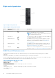


Table Of Contents
- Dell EMC PowerEdge R740xd Installation and Service Manual
- PowerEdge R740xd system overview
- Documentation resources
- Initial system setup and configuration
- Installing and removing system components
- Safety instructions
- Before working inside your system
- After working inside your system
- Recommended tools
- Optional front bezel
- System cover
- Backplane cover
- Inside the system
- Air shroud
- Cooling fan assembly
- Cooling fans
- Intrusion switch
- NVDIMM-N battery
- Mid drive tray
- Mid drive tray details
- Removing mid drive tray
- Installing the mid drive tray
- Removing drive blank from drive carrier
- Installing drive blank into the drive carrier
- Removing drive carrier from the mid drive tray
- Installing drive carrier into mid drive tray
- Removing 3.5 inch drive from the drive carrier
- Installing 3.5 inch drive into the drive carrier
- Removing a 2.5 inch drive from the 3.5 inch mid drive carrier
- Installing a 2.5 inch drive into the 3.5 inch mid drive carrier
- Drives
- Drive guidelines
- Removing a drive blank
- Installing a drive blank
- Removing a drive carrier
- Installing a drive carrier
- Removing a 2.5 inch drive from the 3.5 inch drive adapter
- Installing a 2.5 inch drive into the 3.5 inch drive adapter
- Removing a 3.5 inch adapter from a 3.5 inch drive carrier
- Installing a 3.5 inch adapter into a 3.5 inch drive carrier
- Removing the drive from the drive carrier
- Installing a drive into the drive carrier
- Rear drive cage
- System memory
- Processors and heat sinks
- Expansion cards and expansion card risers
- Expansion card installation guidelines
- Opening and closing the PCIe card holder latch
- Removing expansion card from the expansion card riser
- Installing expansion card into the expansion card riser
- Removing riser 2 and 3 blank
- Installing riser 2 and 3 blank
- Removing riser 3 blank
- Installing riser 3 blank
- Removing expansion card riser 1
- Installing expansion card riser 1
- Removing expansion card riser 2
- Installing expansion card riser 2
- Removing expansion card riser 3
- Installing expansion card riser 3
- GPU card installation guidelines
- Removing a GPU
- Installing a GPU
- M.2 SSD module
- Optional MicroSD or vFlash card
- Optional IDSDM or vFlash module
- Network daughter card
- Integrated storage controller card
- Backplane
- Backplane details
- Removing the backplane
- Installing the backplane
- Removing mid drive tray backplane
- Installing mid drive tray backplane
- Removing the 3.5 inch drive rear backplane
- Installing the 3.5 inch drive rear backplane
- Removing the 2.5 inch drive rear backplane
- Installing the 2.5 inch drive rear backplane
- Cable routing
- System battery
- Optional internal USB memory key
- Power supply units
- System board
- Trusted Platform Module
- Control panel
- System diagnostics
- Jumpers and connectors
- Getting help

Table 14. Drive indicator codes (continued)
Drive status indicator code Condition
Off Drive ready for removal.
NOTE: The drive status indicator remains off until all drives
are initialized after the system is turned on. Drives are not
ready for removal during this time.
Flashes green, amber, and then turns off Predicted drive failure.
Flashes amber four times per second Drive failed.
Flashes green slowly Drive rebuilding.
Solid green Drive online.
Flashes green for three seconds, amber for three
seconds, and then turns off after six seconds
Rebuild stopped.
LCD panel
The LCD panel provides system information, status, and error messages to indicate if the system is functioning correctly or
requires attention. The LCD panel can also be used to configure or view the system’s iDRAC IP address. Para obtener
información sobre los mensajes de eventos y errores generados por el firmware del sistema y los agentes que supervisan los
componentes del sistema, consulte qrl.dell.com > Look Up > Error Code, escriba el código de error y, a continuación, haga clic
en Look it up..
The LCD panel is available only on the optional front bezel. The optional front bezel is hot pluggable.
The statuses and conditions of the LCD panel are outlined here:
● The LCD backlight is white during normal operating conditions.
● When the system needs attention, the LCD backlight turns amber, and displays an error code followed by descriptive text.
NOTE:
If the system is connected to a power source and an error is detected, the LCD turns amber regardless of
whether the system is turned on or off.
● When the system turns off and there are no errors, LCD enters the standby mode after five minutes of inactivity. Press any
button on the LCD to turn it on.
● If the LCD panel stops responding, remove the bezel and reinstall it.
If the problem persists, see Getting help.
● The LCD backlight remains off if LCD messaging is turned off using the iDRAC utility, the LCD panel, or other tools.
Figure 14. LCD panel features
Table 15. LCD panel features
Item Button or
display
Description
1 Left Moves the cursor back in one-step increments.
2 Select Selects the menu item highlighted by the cursor.
3 Right Moves the cursor forward in one-step increments.
During message scrolling:
● Press and hold the right button to increase scrolling speed.
● Release the button to stop.
20 PowerEdge R740xd system overview