
Owners Manual


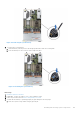


Table Of Contents
- Dell EMC PowerEdge R650 Installation and Service Manual
- Contents
- About this document
- Dell EMC PowerEdge R650 system overview
- Initial system setup and configuration
- Minimum to POST and system management configuration validation
- Installing and removing system components
- Safety instructions
- Before working inside your system
- After working inside your system
- Recommended tools
- Optional front bezel
- System cover
- Drive backplane cover
- Air shroud
- Cooling fans
- Drives
- Drive backplane
- Rear mounting front PERC module
- Rear drive module
- Cable routing
- System memory
- Processor and heat sink module
- Expansion cards and expansion card risers
- Intrusion switch module
- M.2 SSD module on BOSS-S1 adapter card
- Optional BOSS S2 module
- Optional IDSDM module
- MicroSD card
- Optional OCP card
- System battery
- Optional internal USB card
- VGA module
- Power supply unit
- Optional serial COM port
- System board
- Trusted Platform Module
- LOM and rear IO card
- Control panel
- Upgrade Kits
- Jumpers and connectors
- System diagnostics and indicator codes
- Getting help
- Documentation resources

Steps
1. Disconnect the VGA cable from the connector on the system board and open the cable latch.
2. Disconnect the right control panel cable from the system board and move it away to see the VGA module screw on the
system.
NOTE: Ensure that you note the routing of the cables as you remove them from the system board. Route the cable
properly when you replace it to prevent the cable from being pinched or crimped
3. Using Phillips #2 screwdriver, remove the screw on the VGA module.
4. Slide the VGA module out of the system.
NOTE: The numbers on the image do not depict the exact steps. The numbers are for representation of sequence.
128 Installing and removing system components