
Owners Manual


General memory module installation guidelines
NOTE: Memory configurations that fail to observe these guidelines can prevent your system from booting, stop responding
during memory configuration, or operating with reduced memory.
The system supports Flexible Memory Configuration, enabling the system to be configured and run in any valid chipset
architectural configuration. The following are the recommended guidelines for installing memory modules:
● RDIMMs and LRDIMMs must not be mixed.
● x4 and x8 DRAM based memory modules can be mixed. For more information, see the Mode-specific guidelines section.
● Up to three dual- or single-rank RDIMMs can be populated per channel.
● Up to three LRDIMMs can be populated per channel regardless of rank count.
● If memory modules with different speeds are installed, they will operate at the speed of the slowest installed memory
module(s) or slower depending on system DIMM configuration.
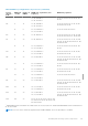
● Populate memory module sockets only if a processor is installed. For single-processor systems, sockets A1 to A12 are
available. For dual-processor systems, sockets A1 to A12 and sockets B1 to B12 are available.
● Populate all the sockets with white release tabs first, followed by the black release tabs, and then the green release tabs.
● When mixing memory modules with different capacities, populate the sockets with memory modules with highest capacity
first. For example, if you want to mix 4 GB and 8 GB memory modules, populate 8 GB memory modules in the sockets with
white release tabs and 4 GB memory modules in the sockets with black release tabs.
● In a dual-processor configuration, the memory configuration for each processor should be identical. For example, if you
populate socket A1 for processor 1, then populate socket B1 for processor 2, and so on.
● Memory modules of different capacities can be mixed provided other memory population rules are followed (for example, 4
GB and 8 GB memory modules can be mixed).
● Mixing of more than two memory module capacities in a system is not supported.
● Populate four memory modules per processor (one DIMM per channel) at a time to maximize performance.
Related references
Mode-specific guidelines on page 82
Mode-specific guidelines
Four memory channels are allocated to each processor. The allowable configurations depend on the memory mode selected.
Advanced Error Correction Code
Advanced Error Correction Code (ECC) mode extends SDDC from x4 DRAM based DIMMs to both x4 and x8 DRAMs. This
protects against single DRAM chip failures during normal operation.
The installation guidelines for memory modules are as follows:
● Memory modules must be identical in size, speed, and technology.
● DIMMs installed in memory sockets with white release levers must be identical and the same rule applies for sockets with
black release levers. This ensures that identical DIMMs are installed in matched pair —for example, A1 with A2, A3 with A4,
A5 with A6, and so on.
Memory optimized independent channel mode
This mode supports Single Device Data Correction (SDDC) only for memory modules that use x4 device width. It does not
impose any specific slot population requirements.
Memory sparing
NOTE: To use memory sparing, this feature must be enabled in System Setup.
In this mode, one rank per channel is reserved as a spare. If persistent correctable errors are detected on a rank, the data from
this rank is copied to the spare rank, and the failed rank is disabled.
82
Installing and removing system components