Dell EMC PowerEdge R540 Installation and Service Manual Regulatory Model: E46S Series Regulatory Type: E46S001 December 2020 Rev.
Notes, cautions, and warnings NOTE: A NOTE indicates important information that helps you make better use of your product. CAUTION: A CAUTION indicates either potential damage to hardware or loss of data and tells you how to avoid the problem. WARNING: A WARNING indicates a potential for property damage, personal injury, or death. © 2018-2020 Dell Inc. or its subsidiaries. All rights reserved. Dell, EMC, and other trademarks are trademarks of Dell Inc. or its subsidiaries.
Contents Chapter 1: Dell EMC PowerEdge R540 overview............................................................................ 7 Supported configurations for the PowerEdge R540 system.................................................................................... 7 Front view of the system...................................................................................................................................................8 Left control panel view............................................
Removing the cooling fan..........................................................................................................................................44 Installing cooling fan................................................................................................................................................... 45 Internal PERC riser...........................................................................................................................................................
Removing the LOM riser card.................................................................................................................................. 99 Installing the LOM riser card...................................................................................................................................100 Drive backplane.................................................................................................................................................................
System board jumpers and connectors......................................................................................................................135 System board jumper settings......................................................................................................................................136 Disabling forgotten password.......................................................................................................................................
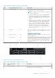
1 Dell EMC PowerEdge R540 overview The Dell EMC PowerEdge R540 system is a 2U, dual socket rack system that supports up to: ● ● ● ● Two Intel Xeon Scalable Processors 16 DIMM slots Two AC and DC redundant power supply units (PSU) or single cabled PSU 14 drives or solid-state drives NOTE: All instances of SAS, SATA hard drives and SSDs are referred to as drives in this document, unless specified otherwise.
Figure 1. Supported configurations for a PowerEdge R540 system with rear drive Front view of the system The front view displays the features available on the front of the system. Figure 2. Front view of 12 x 3.
Table 1. Features available on the front of the system Item Ports, panels, and slots Icon Description `1 Left control panel N/A Contains the system health and system ID, status LED, and the iDRAC Quick Sync 2 (wireless) indicator. NOTE: The iDRAC Quick Sync 2 indicator is available only on certain configurations. ● Status LED: Enables you to identify any failed hardware components. There are up to five status LEDs and an overall system health LED (Chassis health and system ID) bar.
Table 2. Features available on the front of the system (continued) Item Ports, panels, and slots Icon Description NOTE: The iDRAC Quick Sync 2 indicator is available only on certain configurations. ● Status LED: Enables you to identify any failed hardware components. There are up to five status LEDs and an overall system health LED (Chassis health and system ID) bar. For more information, see the Status LED indicators section. ● Quick Sync 2 (wireless): Indicates a Quick Sync enabled system.
Table 3. Left control panel Item Indicator, button, or connector Icon Description 1 Status LED indicators N/A Indicate the status of the system. For more information, see the Status LED indicators on page 11 section. 2 System health and system ID indicator Indicates the system health. 3 iDRAC Quick Sync 2 wireless indicator (optional) Indicates if the iDRAC Quick Sync 2 wireless option is activated. The Quick Sync 2 feature allows management of the system using mobile devices.
System health and system ID indicator codes The system health and system ID indicator is located on the left control panel of your system. Figure 6. System health and system ID indicators Table 5. System health and system ID indicator codes System health and system ID indicator code Condition Solid blue Indicates that the system is turned on, system is healthy, and system ID mode is not active. Press the system health and system ID button to switch to system ID mode.
Table 6. iDRAC Quick Sync 2 indicators and descriptions (continued) iDRAC Quick Sync 2 indicator Condition code Corrective action Solid amber Indicates that the system is in fail-safe mode. Restart the system. If the problem persists, see the Getting help section. Blinking amber Indicates that the iDRAC Quick Sync 2 hardware is not responding properly. Restart the system. If the problem persists, see the Getting help section. Right control panel view Figure 7. Right control panel Table 7.
iDRAC Direct LED indicator codes The iDRAC Direct LED indicator lights up to indicate that the port is connected and is being used as a part of the iDRAC subsystem. You can configure iDRAC Direct by using a USB to micro USB (type AB) cable, which you can connect to your laptop or tablet. The following table describes iDRAC Direct activity when the iDRAC Direct port is active: Table 8.
Table 9. Drive indicator codes (continued) Drive status indicator code Condition Flashes amber four times per second Drive failed. Flashes green slowly Drive rebuilding. Solid green Drive online. Flashes green for three seconds, amber for three seconds, and then turns off after six seconds Rebuild stopped. Back panel features This back view displays the features available on the back of the system. Figure 9. Back panel features of 12 x 3.5-inch + 2 x 3.5-inch (rear) drive system Table 10.
Table 10. Back panel features of R540 (continued) Item Features Icon Description about the supported Ethernet or SFP+ ports. For more information, see the PowerEdge R540 Technical Specs at www.dell.com/ poweredgemanuals. 7 Ethernet port (2) Use the Ethernet ports to connect Local Area Networks (LANs) to the system. For more information about the supported Ethernet ports, For more information, see the PowerEdge R540 Technical Specs at www.dell.com/ poweredgemanuals. 8 USB 3.0 port (2) Use the USB 3.
Table 10. Back panel features of R540 (continued) Item Features Icon Description ● If the system stops responding during POST, press and hold the system ID button (for more than five seconds) to enter the BIOS progress mode. Figure 10. Back panel features of 12 x 3.5-inch + 2 x 3.5-inch (rear) drive system Table 11. Back panel features of R540 Item Features Icon Description 1 Serial port 2 Drive (2) N/A Two optional rear drives supported for 12 x 3.5 inch system.
Table 11. Back panel features of R540 (continued) Item Features Icon Description Specs at www.dell.com/ poweredgemanuals. 6 Ethernet port (2) Use the Ethernet ports to connect Local Area Networks (LANs) to the system. For more information about the supported Ethernet ports, For more information, see the PowerEdge R540 Technical Specs at www.dell.com/ poweredgemanuals. 7 USB 3.0 port (2) Use the USB 3.0 port to connect USB devices to the system. These ports are 4-pin, USB 3.0-compliant.
Table 11. Back panel features of R540 (continued) Item Features Icon Description seconds) to enter the BIOS progress mode. Figure 11. Back panel features of 12 x 3.5-inch drive system with butterfly riser Table 12. Back panel features of R540 Item Features Icon Description 1 Serial port 2 Butterfly riser slot N/A Use the card slots to connect full-height PCIe expansion cards on butterfly riser.
Table 12. Back panel features of R540 (continued) Item Features Icon Description 10 Status indicator cable port N/A Enables you to connect the status indicator cable and view system status when the CMA is installed. 11 System identification button Press the system ID button: ● To locate a particular system within a rack. ● To turn the system ID on or off. To reset iDRAC, press and hold the button for more than 15 seconds.
Figure 13. AC PSU status indicator 1. AC PSU status indicator/handle Table 14. AC PSU status indicator codes Power indicator codes Condition Green A valid power source is connected to the PSU and the PSU is operational. Blinking amber Indicates a problem with the PSU. Not illuminated Power is not connected to the PSU. Blinking green When the firmware of the PSU is being updated, the PSU handle blinks green. CAUTION: Do not disconnect the power cord or unplug the PSU when updating firmware.
Figure 14. DC PSU status indicator 1. DC PSU status indicator Table 15. DC PSU status indicator codes Power indicator codes Condition Green A valid power source is connected to the PSU and the PSU is operational. Blinking amber Indicates a problem with the PSU. Not illuminated Power is not connected to the PSU. Blinking green When hot-plugging a PSU, the PSU indicator blinks green.
NOTE: If the system is connected to a power source and an error is detected, the LCD turns amber regardless of whether the system is turned on or off. ● When the system turns off and there are no errors, LCD enters the standby mode after five minutes of inactivity. Press any button on the LCD to turn it on. ● If the LCD panel stops responding, remove the bezel and reinstall it. If the problem persists, see Getting help.
Option Description iDRAC Select DHCP or Static IP to configure the network mode. If Static IP is selected, the available fields are IP, Subnet (Sub), and Gateway (Gtw). Select Setup DNS to enable DNS and to view domain addresses. Two separate DNS entries are available. Set error Select SEL to view LCD error messages in a format that matches the IPMI description in the SEL. This enables you to match an LCD message with an SEL entry.
System information label Figure 17.
Figure 18. Memory information Figure 19. OCP and internal PERC riser installation Figure 20.
Figure 21.
2 Initial system setup and configuration Topics: • • • Setting up your system iDRAC configuration Options to install the operating system Setting up your system Perform the following steps to set up your system: Steps 1. Unpack the system. 2. Install the system into the rack. For more information about installing the system into the rack, see the Rail Installation Guide at www.dell.com/poweredgemanuals. 3. Connect the peripherals to the system. 4. Connect the system to its electrical outlet. 5.
NOTE: To access iDRAC, ensure that you connect the ethernet cable to the iDRAC9 dedicated network port. You can also access iDRAC through the shared LOM mode, if you have opted for a system that has the shared LOM mode enabled.
Table 18. Firmware and drivers (continued) Methods Location Using Dell Server Update Utility (SUU) www.dell.com/openmanagemanuals > Server Update Utility Using Dell OpenManage Deployment Toolkit (DTK) www.dell.com/openmanagemanuals > OpenManage Deployment Toolkit Using iDRAC virtual media www.dell.com/idracmanuals Downloading drivers and firmware Dell EMC recommends that you download and install the latest BIOS, drivers, and systems management firmware on your system.
3 Installing and removing system components Topics: • • • • • • • • • • • • • • • • • • • • • • • • • • • • • • • • • Safety instructions Before working inside your system After working inside your system Recommended tools Optional front bezel System cover Backplane cover Inside the system Air shroud Cooling fans Internal PERC riser Intrusion switch Drives System memory Processors and heat sinks Expansion cards and expansion card risers M.
telephone service and support team. Damage due to servicing that is not authorized by Dell is not covered by your warranty. Read and follow the safety instructions that are shipped with your product. NOTE: It is recommended that you always use an antistatic mat and antistatic strap while working on components inside the system. CAUTION: To ensure proper operation and cooling, all bays in the system and system fans must be always populated with a component or a blank.
Removing the front bezel Prerequisites Follow the safety guidelines listed in Safety instructions on page 31. Steps 1. Unlock the bezel by using the bezel key. 2. Press the release button, and pull the left end of the bezel. 3. Unhook the right end, and remove the bezel. Figure 22. Removing the front bezel with the LCD panel Installing the front bezel Prerequisites Follow the safety guidelines listed in Safety instructions on page 31. Steps 1. Locate and remove the bezel key.
Figure 23. Installing the front bezel with the LCD panel System cover NOTE: The system cover of 12 x 3.5-inch + 2 x 3.5-inch (rear) system is different from other systems. The cover has one additional mylar and foam layer on the front side of the system cover. Removing the system cover Prerequisites 1. Follow the safety guidelines listed in Safety instructions on page 31. 2. Turn off the system, including any attached peripherals. 3.
Figure 24. Removing the system cover Installing the system cover Prerequisites 1. Follow the safety guidelines listed in Safety instructions on page 31. 2. Ensure that all internal cables are routed correctly and connected, and no tools or extra parts are left inside the system. Steps 1. Align the tabs on the system cover with the guide slots on the system. 2. Push the system cover latch down.
Figure 25. Installing system cover Next steps 1. Reconnect the peripherals and connect the system to the electrical outlet. 2. Turn on the system, including any attached peripherals. Backplane cover Removing the backplane cover Prerequisites 1. Follow the safety guidelines listed in Safety instructions on page 31. 2. Follow the procedure listed in Before working inside your system on page 32. 3. Removing the system cover on page 34. Steps 1.
Figure 26. Removing backplane cover Installing the backplane cover Prerequisites 1. Follow the safety guidelines listed in Safety instructions on page 31. 2. Follow the procedure listed in Before working inside your system on page 32. 3. Installing the system cover on page 35. Steps 1. Align the tabs on the backplane cover with the guide slots on the system. 2. Slide the backplane cover toward the front of the system until the cover locks into place.
Figure 27. Installing backplane cover Next steps Follow the procedure listed in After working inside your system on page 32. Inside the system NOTE: Components that are hot swappable are marked orange and touch points on the components are marked blue.
Figure 28.
Figure 29. Inside the system with rear drive cage 1. 3. 5. 7. 9. 11. Information tag Cooling fans CPU 1 System board Internal PERC riser Butterfly riser 13. Low profile riser right 15. Drive cage (rear) 40 Installing and removing system components 2. 4. 6. 8. 10. 12. Drive backplane Memory module CPU 2 LOM riser card Air shroud Air shroud (12 x 3.5 inch + 2 x 3.5 inch rear hard drive system) 14.
Air shroud Removing the air shroud Prerequisites CAUTION: Never operate your system with the air shroud removed. The system may get overheated quickly, resulting in shutdown of the system and loss of data. 1. Follow the safety guidelines listed in Safety instructions on page 31. 2. Follow the procedure listed in Before working inside your system on page 32. 3. If installed, remove the butterfly riser. Steps Hold the air shroud at both ends and lift it away from the system. Figure 30.
Next steps 1. If applicable, Installing the air shroud on page 42 2. Follow the procedure listed in After working inside your system on page 32. Installing the air shroud Prerequisites 1. Follow the safety guidelines listed in Safety instructions on page 31. 2. Follow the procedure listed in Before working inside your system on page 32. 3. If applicable, route the cables inside the system along the system wall and secure the cables by using the cable latch. Steps 1.
Figure 31. Installing air shroud NOTE: The procedure to install the air shroud for 2 x 3.5-inch rear drive system is identical. Next steps 1. If removed, install the butterfly riser.
2. Follow the procedure listed in After working inside your system on page 32. Cooling fans Removing the cooling fan The procedure for removing standard and high performance fans are identical. Prerequisites 1. 2. 3. 4. 5. Follow the safety guidelines listed in Safety instructions on page 31. Follow the procedure listed in Before working inside your system on page 32.
Figure 33. Removing cooling fan Next steps 1. 2. 3. 4. Installing cooling fan on page 45. Installing the internal PERC riser on page 49 Installing the air shroud on page 42 Follow the procedure listed in After working inside your system on page 32. Installing cooling fan The procedure for installing standard and high performance fans are identical. Prerequisites 1. 2. 3. 4. 5. 6. Follow the safety guidelines listed in Safety instructions on page 31.
Figure 34. Installing cooling fan NOTE: In the 12 x 3.5-inch drive system, connect the fan 1 cable to the power interposer board connector.
Figure 35. Connecting fan cable to PIB connector Next steps 1. 2. 3. 4. Installing the internal PERC riser on page 49 Ensure all the cables are routed correctly. Installing the air shroud on page 42 Follow the procedure listed in After working inside your system on page 32. Internal PERC riser Removing the internal PERC riser Prerequisites 1. Follow the safety guidelines listed in Safety instructions on page 31. 2. Follow the procedure listed in Before working inside your system on page 32. 3.
Figure 36. Removing internal PERC riser 5. Turn the internal riser so that the PERC card is facing up. 6. Press the cable connector and disconnect the cable connected to the internal PERC card. Figure 37. Disconnecting the cable from internal PERC card Next steps 1. Installing the air shroud on page 42 2. Follow the procedure listed in After working inside your system on page 32. 3.
Installing the internal PERC riser Prerequisites Follow the safety guidelines listed in Safety instructions on page 31. Steps 1. Connect the cable to the internal PERC card. Figure 38. Connecting the cable to internal PERC riser 2. Holding the blue touch points, align the slot on the internal PERC riser to the guide on the system board. 3. Insert the internal riser card’s edge connector firmly into the system board connector until the riser is fully seated. 4. Lift the plunger to lock the riser in place.
Figure 39. Installing internal PERC riser 5. Connect the cables to the backplane and then route the cables to the cable guiding latch to close the latch. Next steps 1. Installing the air shroud on page 42 2. Follow the procedure listed in After working inside your system on page 32. Removing the PERC card from the internal PERC riser Prerequisites 1. 2. 3. 4. Follow the safety guidelines listed in Safety instructions on page 31. Follow the procedure listed in Before working inside your system on page 32.
Figure 40. Removing the PERC card from the internal PERC riser Next steps 1. Installing the internal PERC riser on page 49 2. Installing the air shroud on page 42 3. Follow the procedure listed in After working inside your system on page 32. Installing PERC card into the internal PERC riser Prerequisites 1. Follow the safety guidelines listed in Safety instructions on page 31. Steps 1. Insert the PERC card into the internal PERC riser and push the card in. 2.
Figure 41. Installing PERC card into internal PERC riser Next steps 1. Installing the internal PERC riser on page 49 2. Installing the air shroud on page 42 3. Follow the procedure listed in After working inside your system on page 32. Intrusion switch Removing the intrusion switch Prerequisites 1. 2. 3. 4. Follow the safety guidelines listed in Safety instructions on page 31. Follow the procedure listed in Before working inside your system on page 32.
Figure 42. Removing an intrusion switch Next steps Installing the intrusion switch on page 53. Installing the intrusion switch Prerequisites 1. Follow the safety guidelines listed in Safety instructions on page 31. 2. Follow the procedure listed in Before working inside your system on page 32. Steps 1. Align the intrusion switch with the intrusion switch slot.
Figure 43. Installing intrusion switch 2. Slide the intrusion switch until it is firmly seated in the intrusion switch slot. 3. Connect the intrusion switch cable to the connector on the system board. Next steps 1. Installing the internal PERC riser on page 49 2. Follow the procedure listed in After working inside your system on page 32. Drives The PowerEdge R540 system supports: ● Up to 14 x 3.5 inch drives or 2.
Figure 44. Removing a drive blank Next steps 1. Installing a drive blank on page 55 Installing a drive blank The procedure for installing 2.5-inch and 3.5-inch drive blanks is identical. Prerequisites 1. Follow the safety guidelines listed in Safety instructions on page 31. 2. If installed, Removing the front bezel on page 33 CAUTION: Mixing drive blanks from previous generations of PowerEdge servers is not supported.
NOTE: A 2.5 inch drive is installed in a 3.5 inch drive adapter, which is then installed in the 3.5-inch drive carrier. Steps 1. Using a Phillips #2 screwdriver, remove the screws from the side of the 3.5-inch drive adapter. NOTE: If the hard drive or SSD carrier has Torx screw, use Torx 6 screwdriver to remove the drive. 2. Remove the 2.5-inch drive from the 3.5-inch drive adapter. Figure 46. Removing a 2.5 inch drive from a 3.5-inch drive adapter Next steps Installing a 2.5-inch drive into a 3.
Figure 47. Installing a 2.5-inch drive into a 3.5-inch drive adapter Removing a 3.5-inch drive adapter from a 3.5-inch drive carrier Prerequisites 1. Follow the safety guidelines listed in Safety instructions on page 31. 2. If installed, Removing the front bezel on page 33 3. Remove the 3.5-inch drive carrier from the system. Steps 1. Using a Phillips #1 screwdriver, remove the screws from the rails on the drive carrier. NOTE: If the 3.
Figure 48. Removing a 3.5-inch drive adapter from a 3.5-inch drive carrier Next steps Installing a 3.5-inch drive adapter into the 3.5-inch drive carrier on page 58 Installing a 3.5-inch drive adapter into the 3.5-inch drive carrier Prerequisites 1. Follow the safety guidelines listed in Safety instructions on page 31. 2. Install the 2.5-inch drive into the 3.5-inch drive adapter. Steps 1. Insert the 3.5-inch drive adapter into the 3.
Figure 49. Installing a 3.5-inch drive adapter into the 3.5-inch drive carrier Next steps 1. Install the 3.5-inch drive carrier into the system. 2. If removed, install the front bezel. Removing a drive carrier Prerequisites 1. Follow the safety guidelines listed in Safety instructions on page 31. 2. If applicable, remove the front bezel. 3. Using the management software, prepare the drive for removal. If the drive is online, the green activity or fault indicator flashes while the drive is turning off.
Figure 50. Removing a drive carrier Next steps 1. Follow the procedure listed in After working inside your system on page 32. 2. Install a drive carrier. 3. If you are not replacing the drive immediately, Insert a drive blank in the empty drive slot to maintain proper system cooling.
Figure 51. Installing a drive carrier Next steps If applicable, install the front bezel. Removing the drive from the drive carrier Prerequisites CAUTION: Mixing drives from previous generations of PowerEdge servers is not supported. Steps 1. Using a Phillips #1 screwdriver, remove the screws from the slide rails on the drive carrier. 2. Lift the drive out of the drive carrier. Figure 52.
Next steps If applicable, Installing a drive into the drive carrier on page 62 Installing a drive into the drive carrier Prerequisites CAUTION: Mixing drive carriers from other generations of PowerEdge servers is not supported. NOTE: When installing a drive into the drive carrier, ensure that the screws are torqued to 4 in-lbs. Steps 1. Insert the drive into the drive carrier with the connector end of the drive towards the back of the carrier. 2.
Figure 54. Memory socket locations Memory channels are organized as follows: Table 19.
● RDIMMs and LRDIMMs must not be mixed. ● 64 GB LRDIMMs that are DDP (Dual Die Package) LRDIMMs must not be mixed with 128 GB LRDIMMs that are TSV (Through Silicon Via/3DS) LRDIMMs. ● x4 and x8 DRAM based memory modules can be mixed. ● Up to two RDIMMs can be populated per channel regardless of rank count. ● Up to two LRDIMMs can be populated per channel regardless of rank count. ● A maximum of two different ranked DIMMs can be populated in a channel regardless of rank count.
Table 20. Memory operating modes (continued) Memory Operating Mode Description uncorrectable failure. Requires two or more ranks to be populated in each channel. Multi Rank Spare Mode Multi Rank Spare Mode allocates two ranks per channel as a spare. If excessive correctable errors occur in a rank or channel, while the operating system is running, they are moved to the spare area to prevent errors from causing an uncorrectable failure. Requires three or more ranks to be populated in each channel.
Table 21. Memory population rules (continued) Processor Configuration Memory population Memory population information configurations, which in turn will result in performance loss. It is recommended to populate all memory channels identically with identical DIMMs for best performance. ● Optimizer population order is not traditional for 4 and 8 DIMM installations of single processor.
Table 21. Memory population rules (continued) Processor Configuration Memory population Memory population information Multi rank sparing population order A{1}, B{1}, A{2}, B{2}, A{3}, B{3}... Populate in this order, odd amount per processor allowed. Requires three ranks or more per channel. Removing a memory module Prerequisites 1. Follow the safety guidelines listed in Safety instructions on page 31. 2. Follow the procedure listed in Before working inside your system on page 32. 3.
3. Align the edge connector of the memory module with the alignment key of the memory module socket, and insert the memory module in the socket. CAUTION: Do not apply pressure at the center of the memory module; apply pressure at both ends of the memory module evenly. NOTE: The memory module socket has an alignment key that enables you to install the memory module in the socket in only one orientation. 4. Press the memory module with your thumbs until the socket levers firmly click into place. Figure 56.
b. Loosen the second screw completely. c. Return to the first screw and loosen it completely. 2. Pushing both blue retention clips simultaneously, lift the processor and heat sink module (PHM) processor and heat sink module 3. Set the PHM aside with the processor side facing up. Figure 57.
Figure 58. Loosening the processor bracket 4. Lift the bracket and the processor away from the heat sink, and place the processor connector side down on the processor tray. 5. Flex the outer edges of the bracket to release the bracket from the processor. NOTE: Ensure that the processor and the bracket are placed in the tray after you remove the heat sink. Figure 59.
Installing the non-fabric processor into a processor and heat sink module Prerequisites Follow the safety guidelines listed in Safety instructions on page 31. Steps 1. Place the processor in the processor tray. NOTE: Ensure that the pin 1 indicator on the processor tray is aligned with the pin 1 indicator on the processor. 2. Flex the outer edges of the bracket around the processor ensuring that the processor is locked into the clips on the bracket.
Figure 61. Applying thermal grease on top of the processor 5. Place the heat sink on the processor and push down on the base of the heat sink until the bracket locks onto the heat sink. NOTE: ● Ensure that the two guide pin holes on the bracket match the guide holes on the heat sink. ● Do not press on the heat sink fins. ● Ensure that the pin 1 indicator on the heat sink is aligned with the pin 1 indicator on the bracket before placing the heat sink onto the processor and bracket.
Figure 62. Installing the heat sink onto the processor Next steps 1. Installing a processor and heat sink module on page 73 2. Installing the air shroud on page 42 3. Follow the procedure listed in After working inside your system on page 32. Installing a processor and heat sink module Prerequisites CAUTION: Never remove the heat sink from a processor unless you intend to replace the processor. The heat sink is necessary to maintain proper thermal conditions. 1.
b. Tighten the second screw completely. c. Return to the first screw and tighten it completely. If the PHM slips off the blue retention clips when the screws are partially tightened, follow these steps to secure the PHM: a. Loosen both the heat sink screws completely. b. Lower the PHM on to the blue retention clips, following the procedure described in step 2. c. Secure the PHM to the system board, following the replacement instructions listed in this step above. 4. Figure 63.
NOTE: The expansion-card slots are not hot-swappable. The following table provides guidelines for installing expansion cards to ensure proper cooling and mechanical fit. The expansion cards with the highest priority should be installed first using the slot priority indicated. All the other expansion cards should be installed in the card priority and slot priority order. Table 23.
Table 25. Riser configurations: FH - 1 CPU and 2 CPU (continued) Card type Slot priority Form factor NIC (Broadcom/INTEL/EMULEX/ Mellanox/Solarflare) 2 FH Card,Network (Broadcom/INTEL/ Mellanox/INTEL) 2 FH Card,Controller (EMULEX/QLOGIC) 2 FH Intel OPA NIC (Intel OPA) 2 FH BOSS M.2 (SATA) (Dell) 2 FH PERC9.14G/PERC10 (ODM) Integrated Slot NONE RAID - PERC9.14G/PERC10 (Internal) (Dell) Integrated Slot NONE Table 26.
Table 27. Riser configurations: BTF + 3 XLP - 1 CPU (continued) Card type Slot priority Form factor Card,Network (Broadcom/INTEL/ Mellanox/QLOGIC/Solarflare) 3, 5 LP Card,Controller (QLOGIC) 3, 5 LP Intel OPA NIC (Intel OPA) 2 FH BOSS M.2 (SATA) (Dell) 3, 5 LP Card,Network (Broadcom) 6, 5, 3 LP Card,Network (INTEL) 6, 5, 3 LP PERC9.14G/PERC10 (ODM) Integrated Slot NONE RAID - PERC9.14G/PERC10 (Internal) (Dell) Integrated Slot NONE Table 28.
Removing expansion card from the expansion card riser Prerequisites 1. 2. 3. 4. 5. Follow the safety guidelines listed in Safety instructions on page 31. Follow the procedure listed in Before working inside your system on page 32. If applicable, Removing the air shroud on page 41. If applicable, disconnect the cables from the expansion card. When removing a card from low profile, full height X1, or butterfly riser, ensure that the PCIe card holder latch is closed. Steps 1.
Figure 65. Removing expansion card from full height X1 riser Figure 66. Removing expansion card from butterfly riser 3. If the expansion card is not going to be replaced, install a filler bracket.
Figure 67. Installing filler bracket for low profile riser Figure 68.
Figure 69. Installing filler bracket for butterfly riser Next steps 1. Install expansion card into the expansion card riser. 2. If you are removing the card permanently, install a metal filler bracket over the empty expansion slot opening and push the expansion card latch. NOTE: You must install a filler bracket over an empty expansion card slot to maintain Federal Communications Commission (FCC) certification of the system.
Figure 70. Removing filler bracket for low profile riser Figure 71.
Figure 72. Removing filler bracket for butterfly riser 3. Hold the card by its edges, and align the card edge connector with the expansion card connector on the riser. 4. Insert the card edge connector firmly into the expansion card connector until the card is fully seated. 5. Close the expansion card retention latch. Figure 73.
Figure 74. Installing expansion card into full height X1 riser Figure 75. Installing expansion card into butterfly riser Next steps 1. 2. 3. 4. 84 If applicable, connect the cables to the expansion card. If applicable, install air shroud. Follow the procedure listed in After working inside your system on page 32. Install any device drivers required for the card as described in the documentation for the card.
Removing expansion card from the system board Prerequisites 1. Follow the safety guidelines listed in Safety instructions on page 31. 2. Follow the procedure listed in Before working inside your system on page 32. 3. Disconnect any cables connected to the expansion card. Steps 1. Pull and lift up the expansion card retention latch lock to open. 2. Hold the expansion card by the edge and pull the card to disconnect from the system board connector. Figure 76. Removing expansion card from system board 3.
Figure 77. Installing the filler bracket NOTE: Filler brackets must be installed over empty expansion card slots to maintain FCC certification of the system. The brackets also keep dust and dirt out of the system and aid in proper cooling and airflow inside the system. Next steps 1. Install the expansion card on the system board Installing expansion card on the system board Prerequisites 1. Follow the safety guidelines listed in Safety instructions on page 31. Steps 1.
Figure 78. Removing the filler bracket NOTE: Store the filler bracket for future use. Filler brackets must be installed in empty expansion card slots to maintain FCC certification of the system. The brackets also keep dust and dirt out of the system and aid in proper cooling and airflow inside the system. 3. Holding the card on the edges, align the card with the expansion card connector on the system board. 4.
Figure 79. Installing expansion card on system board Next steps 1. Connect the required cables to the expansion card. 2. Follow the procedure listed in After working inside your system on page 32. Removing an expansion card riser Prerequisites 1. Follow the safety guidelines listed in Safety instructions on page 31. 2. Follow the procedure listed in Before working inside your system on page 32. 3. Disconnect any cables connected to the expansion card.
Figure 80. Removing low profile riser right Figure 81.
Figure 82. Removing full height X1 riser NOTE: For butterfly riser, loosen the captive screw and holding the touch points lift the riser away from the system. Figure 83. Removing butterfly riser Next steps Install the expansion card riser.
Installing an expansion card riser Prerequisites 1. Follow the safety guidelines listed in Safety instructions on page 31. Steps 1. If removed, install the expansion cards into the expansion card riser. 2. Holding the touch points, align the expansion card riser with the connector and the riser guide pin on the system board. 3. Lower the expansion card riser into place until the expansion card riser connector is fully seated in the connector. Figure 84.
Figure 85. Installing low profile riser left Figure 86. Installing full height X1 riser NOTE: For butterfly riser, tighten the captive screw to firmly hold the riser to the system board.
Figure 87. Installing butterfly riser Next steps 1. Follow the procedure listed in After working inside your system on page 32. 2. Install any device drivers required for the card as described in the documentation for the card. M.2 SSD module Removing the M.2 SSD module Prerequisites 1. 2. 3. 4. 5. Follow the safety guidelines listed in Safety instructions on page 31. Follow the procedure listed in Before working inside your system on page 32. Remove the air shroud.
Figure 88. Removing the M.2 SSD module Next steps Replace the M.2 SSD module. Installing the M.2 SSD module Prerequisites 1. 2. 3. 4. Follow the safety guidelines listed in Safety instructions on page 31. Follow the procedure listed in Before working inside your system on page 32. Remove the air shroud. Remove the BOSS card NOTE: The procedure to remove the BOSS card is similar to the removing an expansion card. Steps 1. Connect the M.2 SSD module to the connector on the BOSS card. 2.
Figure 89. Installing the M.2 SSD module Next steps 1. Install the BOSS card. NOTE: The procedure to install the BOSS card is similar to the Installing expansion card on the system board on page 86. 2. Install the applicable air shroud. 3. Follow the procedure listed in After working inside your system. Optional MicroSD or vFlash card Removing the MicroSD card Prerequisites 1. Follow the safety guidelines listed in Safety instructions on page 31. 2.
Figure 90. Removing the MicroSD card NOTE: Temporarily label each MicroSD card with its corresponding slot number after removal. Next steps 1. Follow the procedure listed in After working inside your system on page 32. 2. Installing the MicroSD card on page 96 Installing the MicroSD card Prerequisites Follow the safety guidelines listed in Safety instructions on page 31. NOTE: To use an MicroSD card with your system, ensure that the Internal SD Card Port is enabled in System Setup.
Figure 91. Installing the MicroSD card Next steps Follow the procedure listed in After working inside your system on page 32. Optional IDSDM or vFlash module Removing the optional IDSDM or vFlash card Prerequisites 1. Follow the safety guidelines listed in Safety instructions on page 31. 2. Follow the procedure listed in Before working inside your system on page 32. Steps 1. Locate the IDSDM/vFlash connector on the system board.
Figure 92. Removing the optional IDSDM/vFlash card NOTE: There are two dip switches on the IDSDM/vFlash card for write-protection. Next steps Installing optional IDSDM or vFlash card on page 98 Installing optional IDSDM or vFlash card Prerequisites Follow the safety guidelines listed in Safety instructions on page 31. Steps 1. Locate the IDSDM/vFlash connector on the system board. To locate IDSDM/vFlash connector, see the Jumpers and connectors on page 135 section. 2.
Figure 93. Installing optional IDSDM/vFlash card Next steps 1. Install the MicroSD cards. NOTE: Reinstall the MicroSD cards into the same slots based on the labels you had marked on the cards during removal. 2. Follow the procedure listed in After working inside your system on page 32. LOM riser card Removing the LOM riser card Prerequisites 1. 2. 3. 4. Follow the safety guidelines listed in Safety instructions on page 31. Follow the procedure listed in Before working inside your system on page 32.
Figure 94. Removing LOM riser card Next steps Installing the LOM riser card on page 100 Installing the LOM riser card Prerequisites Follow the safety guidelines listed in Safety instructions on page 31. Steps 1. Align the connectors on the LOM riser card with the slot on the system. 2. Press the LOM riser card until the card is firmly seated on the system board connector and the two blue plastic snap hold the LOM riser card in place. 3.
Figure 95. Installing LOM riser card Next steps 1. If removed, install the risers. 2. If removed, install the rear drive cage. 3. Follow the procedure listed in After working inside your system on page 32. Drive backplane Backplane details Depending on your system configuration, the drive backplanes supported in PowerEdge R540 are listed here: Table 29. Supported backplane options for PowerEdge R540 systems System Supported hard drives options 3.5 inch (x8) SAS, SATA backplane PowerEdge R540 3.
Figure 96. 8 X 3.5 inch drive backplane 1. SAS/SATA B cable connector 3. SAS/SATA A cable connector 2. Signal connector 4. Power connector Figure 97. 12 X 3.5 inch drive backplane 1. Power cable connector 3. SAS/SATA cable connector 5. SAS cable connector Figure 98. 2 x 3.5 inch drive backplane (rear) 1. Power connector 2. Signal connector 3. SAS cable connector 102 Installing and removing system components 2. SAS/SATA cable connector 4.
Removing the backplane Prerequisites CAUTION: To prevent damage to the drives and backplane, remove the drives from the system before removing the backplane. CAUTION: Note the number of each drive and temporarily label them before you remove the drive so that you can replace them in the same location. NOTE: The procedure to remove the backplane is similar for all backplane configurations. 1. 2. 3. 4. 5. 6. Follow the safety guidelines listed in Safety instructions on page 31.
Installing the backplane Prerequisites Follow the safety guidelines listed in Safety instructions on page 31. NOTE: The procedure to install the backplane is similar for all backplane configurations. Steps 1. Use the hooks on the system as guides to align the slots on the backplane with the guides on the system. 2. Lower the drive backplane until the blue release tabs snap into place. Figure 101. Installing the backplane Next steps 1. 2. 3. 4. 5. Connect all the cables to the backplane.
1. 2. 3. 4. 5. Follow the safety guidelines listed in Safety instructions on page 31. Follow the procedure listed in Before working inside your system on page 32. Remove all the drives from the rear drive cage. Disconnect all the cables from the backplane. Remove the rear drive cage. Steps 1. Using Phillips #2 screwdriver, remove the screws that secure the drive backplane to the rear drive cage. 2. Disengage the backplane from the hooks on the rear drive cage, and remove it from the rear drive cage.
Figure 103. Installing 3.5-inch rear drive backplane Next steps 1. 2. 3. 4. Install the rear drive cage. Install all the drives. Connect all the cables to the backplane. Follow the procedure listed in After working inside your system on page 32.
Cable routing Figure 104. Cable routing - 12 x 3.5-inch drive backplane and 2 x 3.5-inch rear drive backplane with internal PERC riser 1. Drive backplane 3. Internal PERC riser 5. Cable guiding latch 2. SAS cable (BP: SAS A2 to rear drive backplane) 4. Drive backplane (rear) 6.
Figure 105. Cable routing - 8 x 3.5-inch drive backplane with internal PERC riser 1. Drive backplane 3. Internal PERC riser 5. SATA cable (BP: BP_B to internal PERC riser: SATA_B) 2. SATA cable (BP: BP_A to internal PERC riser: SATA_A) 4. Cable guiding latch Figure 106. Cable routing - 12 x 3.5-inch drive backplane 1. Drive backplane 3. SATA B cable (BP: BP_B0 to MB: SATA_B) 108 Installing and removing system components 2. SATA A cable (BP: BP_A0 to MB: SATA_A) 4.
5. Cable guiding latch 6. SATA C cable (BP: BP_C0 to MB: SATA_C) Figure 107. Cable routing - 8 x 3.5-inch drive backplane 1. Drive backplane 3. SATA B cable (BP: BP_B to MB: SATA_B) 5. Cable guiding latch 2. SATA A cable (BP: BP_A to MB: SATA_A) 4.
Figure 108. Cable routing - 2 x 3.5-inch Hybrid backplane with NVMe U.2 SSD 1. 3. 5. 7. 9. drive backplane backplane power cable SATA cable (BP:BP_C0 to MB SATA_C1) Power interposer board (PIB) PCIe cable (BP:BP PCIe A0 to MB PCIe_A0) 2. 4. 6. 8. backplane signal cable (BP:BP_SIG1 to MB:BP_SIG1) SATA cable (BP:BP_B0 to MB SATA_B1) SATA cable (BP:BP_A0 to MB SATA_A1) PCIe cable (BP:BP PCIe B0 to MB Interposer_A) Rear drive cage Removing the rear drive cage Prerequisites 1. 2. 3. 4.
Figure 109. Removing the rear drive cage Next steps Install the rear drive cage. Installing the rear drive cage Prerequisites Follow the safety guidelines listed in Safety instructions on page 31. Steps 1. Align the screws on the drive cage with the screw holes on the system chassis. 2. Lower the drive cage into the system until it is firmly seated and the screws locks into place. 3. Using Phillips #2 screwdriver, tighten the screws.
Figure 110. Installing the rear drive cage Next steps 1. Reconnect all the disconnected cables to the rear drive backplane. 2. Install all the drives. 3. Follow the procedure listed in After working inside your system on page 32. System battery Replacing the system battery Prerequisites WARNING: There is a danger of a new battery exploding if it is incorrectly installed. Replace the battery only with the same or equivalent type recommended by the manufacturer.
Figure 111. Removing the system battery 3. To install a new system battery, hold the battery with the positive side facing up and slide it under the securing tabs. 4. Press the battery into the connector until it snaps into place. Figure 112. Installing the system battery Next steps 1. 2. 3. 4. 5. 6. If removed, Install the low profile or full height X1 expansion card risers. If applicable, connect the cables to the expansion card(s).
Next steps 1. If removed, Install the low profile expansion card riser. 2. Follow the procedure listed in After working inside your system on page 32. 3. While booting, press F2 to enter System Setup and verify that the system detects the USB memory key. Optical drive (optional) Removing the optical drive Prerequisites 1. 2. 3. 4. Follow the safety guidelines listed in Safety instructions on page 31. Follow the procedure listed in Before working inside your system on page 32.
Installing the optical drive Prerequisites Follow the safety guidelines listed in Safety instructions on page 31. Steps 1. Align the optical drive with the optical drive slot on the front of the system. 2. Slide in the optical drive until the release tab snaps into place. Figure 114. Installing the optical drive Next steps 1. Connect the power and data cables to the connector on the optical drive and the connector on the system board.
Hot spare feature Your system supports the hot spare feature that significantly reduces the power overhead associated with power supply unit (PSU) redundancy. When the hot spare feature is enabled, one of the redundant PSUs is switched to the sleep state. The active PSU supports 100 percent of the load, thus operating at higher efficiency. The PSU in the sleep state monitors output voltage of the active PSU.
Figure 116. Installing a power supply unit blank Next steps Follow the procedure listed in After working inside your system on page 32. Removing a power supply unit The procedure for removing AC and DC PSUs is identical. Prerequisites CAUTION: The system needs one power supply unit (PSU) for normal operation. On power-redundant systems, remove and replace only one PSU at a time in a system that is powered on. 1. Follow the safety guidelines listed in Safety instructions on page 31. 2.
Next steps Installing a processor and heat sink module on page 73 Installing a power supply unit The procedure for installing AC and DC PSUs is identical. Prerequisites 1. Follow the safety guidelines listed in Safety instructions on page 31. 2. For systems that support redundant PSU, ensure that both the PSUs are of the same type and have the same maximum output power. NOTE: The maximum output power (shown in watts) is listed on the PSU label.
3. 4. 5. 6. Removing the air shroud on page 41. Disconnect the system from the electrical outlet. Disconnect all the cables connected from the PSU to the system board. If applicable, Removing an expansion card riser on page 88 Steps 1. Using a Phillips #2 screwdriver, remove the screw securing the PSU to the system. 2. Slide the PSU out of the PSU cage. Figure 119. Removing non-redundant cabled AC PSU Next steps 1.
Figure 120. Installing non-redundant cabled AC PSU Next steps 1. 2. 3. 4. Connect the PSU cables to the connectors on the system board. If applicable, Installing an expansion card riser on page 91 Installing the air shroud on page 42 Follow the procedure listed in After working inside your system on page 32.
Installing DC power supply unit Prerequisites NOTE: For equipment using –(48–60) V DC power supply units (PSUs), a qualified electrician must perform all connections to DC power and to safety grounds. Do not attempt connecting to DC power or installing grounds yourself. All electrical wiring must comply with applicable local or national codes and practices. Damage due to servicing that is not authorized by Dell is not covered by your warranty.
● #6-32 nut equipped with lock washer (1) Required tools Wire-stripper pliers capable of removing insulation from size 10 AWG solid or stranded, insulated copper wire. NOTE: Use alpha wire part number 3080 or equivalent (65/30 stranding). Required wires ● One UL 10 AWG, 2 m maximum (stranded) black wire [–(48–60) V DC]. ● One UL 10 AWG, 2 m maximum (stranded) red wire (V DC return). ● One UL 10 AWG, 2 m maximum, green with a yellow stripe, stranded wire (safety ground).
Power interposer board Removing power interposer board Prerequisites 1. 2. 3. 4. Follow the safety guidelines listed in Safety instructions on page 31. Follow the procedure listed in Before working inside your system on page 32. Removing the air shroud on page 41 Disconnect all the cables connected from the PIB to the system board. NOTE: Ensure that you note the routing of the cables as you remove them from the system board. 5. Removing a processor and heat sink module on page 68 Steps 1.
Steps 1. Align the slots on the PIB with the hook on the PSU cage and slide it into place. 2. Using a Phillips #2 screwdriver, tighten the screw to secure the PIB to the system. 3. Route the cables and connect it to the system board. Figure 122. Installing power interposer board Next steps 1. Installing a processor and heat sink module on page 73 2. Installing the air shroud on page 42 3. Follow the procedure listed in After working inside your system on page 32.
Figure 123. Removing left control panel 3. Holding by the sides, remove the left control panel assembly away from the system. Next steps Installing the left control panel on page 125 Installing the left control panel Prerequisites Follow the safety guidelines listed in Safety instructions on page 31. Steps 1. Route the control panel cable through the side wall of the system. 2. Align the left control panel assembly with the control panel slot on the system and place the assembly in the slot on the system.
Figure 124. Installing left control panel Next steps 1. Installing the air shroud on page 42 2. Installing PERC card into the internal PERC riser on page 51 3. Follow the procedure listed in After working inside your system on page 32. Removing the right control panel Prerequisites 1. Follow the safety guidelines listed in Safety instructions on page 31. 2. Follow the procedure listed in Before working inside your system on page 32. 3.
Figure 125. Removing right control panel 3. Holding by the sides, remove the right control panel assembly away from the system. Next steps Installing the right control panel on page 127 Installing the right control panel Prerequisites Follow the safety guidelines listed in Safety instructions on page 31. Steps 1. Route the control panel cable through the side wall of the system. 2.
Figure 126. Installing right control panel Next steps 1. Installing PERC card into the internal PERC riser on page 51 2. Follow the procedure listed in After working inside your system on page 32. System board Removing the system board Prerequisites CAUTION: If you are using Trusted Platform Module (TPM) with an encryption key, you may be prompted to create a recovery key during program or System Setup. Be sure to create and safely store this recovery key.
d. e. f. g. h. vFlash/IDSDM module Internal USB key (if installed) USB 3.0 module (if installed) Processors and heat sink modules Processors blanks (if installed) CAUTION: To prevent damage to the processor socket when replacing a faulty system board, ensure that you cover the processor socket with the processor dust cover. i. Memory modules j. LOM riser card k. Drive cage (rear) (if installed) Steps 1. Disconnect all cables from the system board.
Figure 128. Removing the system board Next steps Installing the system board on page 130. Installing the system board Prerequisites Follow the safety guidelines listed in Safety instructions on page 31. Steps 1. Unpack the new system board assembly. CAUTION: Do not lift the system board by holding a memory module, processor, or other components. CAUTION: Take care not to damage the system identification button while placing the system board into the chassis. 2.
Figure 129. Installing system board Next steps 1. Replace the following: a. Upgrading the Trusted Platform Module on page 133 b. Installing PERC card into the internal PERC riser on page 51 c. Optional internal USB memory key on page 113) d. USB 3.0 module (if applicable) e. IDSDM/vFlash module card f. All expansion cards and risers g. Processors and heat sink modules h. Processors blanks (if applicable) i. Memory modules j. LOM riser card k. Air shroud l. Drive cage (rear) (if applicable) 2.
Restoring the system using Easy Restore The easy restore feature enables you to restore your service tag, license, UEFI configuration, and the system configuration data after replacing the system board. All data is backed up in a backup flash device automatically. If BIOS detects a new system board, and the service tag in the backup flash device, BIOS prompts the user to restore the backup information.
For more information, see the Integrated Dell Remote Access Controller User's Guide at www.dell.com/poweredgemanuals . Trusted Platform Module Upgrading the Trusted Platform Module Prerequisites 1. Follow the safety guidelines listed in Safety instructions on page 31. 2. Follow the procedure listed in Before working inside your system on page 32. NOTE: ● Ensure that your operating system supports the version of the TPM module being installed.
Figure 130. Installing the TPM Next steps 1. Install the system board. 2. Follow the procedure listed in After working inside your system on page 32. Initializing TPM for BitLocker users Steps Initialize the TPM. For more information, see http://technet.microsoft.com/en-us/library/cc753140.aspx. The TPM Status changes to Enabled, Activated. Initializing the TPM 1.2 for TXT users Steps 1. While booting your system, press F2 to enter System Setup. 2.
4 Jumpers and connectors This topic provides specific information about the jumpers. It also provides some basic information about jumpers and switches and describes the connectors on the various boards in the system. Jumpers on the system board help to disable the system and setup passwords. You must know the connectors on the system board to install components and cables correctly.
Table 30. System board jumpers and connectors Item Connector Description 1. FAN6 Cooling fan 6 connector 2. CPU1 Processor socket 1 3. CPU1_PWR_CONN(P2) CPU1 power connector 4. J_INTRU Intrusion switch connector 5. J_BP_SIG1 Backplane signal connector 1 6. LFT_CP_CONN Left control panel connector 7. J_SATA_B1 Internal SATA B connector 8. RGT_CP_CONN Right panel connector 9. SYS_PWR_CONN(P1) System power connector 10. J_PIB_SIG1 Power interface board signal connector 1 11.
Disabling forgotten password The software security features of the system include a system password and a setup password. The password jumper enables or disables password features and clears any password(s) currently in use. Prerequisites CAUTION: Many repairs may only be done by a certified service technician. You should only perform troubleshooting and simple repairs as authorized in your product documentation, or as directed by the online or telephone service and support team.
5 System diagnostics If you experience a problem with your system, run the system diagnostics before contacting Dell for technical assistance. The purpose of running system diagnostics is to test your system hardware without using additional equipment or risking data loss. If you are unable to fix the problem yourself, service and support personnel can use the diagnostics results to help you solve the problem.
System diagnostic controls Menu Description Configuration Displays the configuration and status information of all detected devices. Results Displays the results of all tests that are run. System health Provides the current overview of the system performance. Event log Displays a time-stamped log of the results of all tests run on the system. This is displayed if at least one event description is recorded.
6 Getting help Topics: • • • • • Contacting Dell EMC Documentation feedback Accessing system information by using QRL Receiving automated support with SupportAssist Recycling or End-of-Life service information Contacting Dell EMC Dell EMC provides several online and telephone based support and service options. If you do not have an active internet connection, you can find contact information about your purchase invoice, packing slip, bill, or Dell EMC product catalog.
● Reference materials, including the Installtion and Service Manual, LCD diagnostics, and mechanical overview ● Your system service tag to quickly access your specific hardware configuration and warranty information ● A direct link to Dell to contact technical assistance and sales teams Steps 1. Go to www.dell.com/qrl and navigate to your specific product or 2. Use your smartphone or tablet to scan the model-specific Quick Resource (QR) code on your system or in the Quick Resource Locator section.
7 Documentation resources This section provides information about the documentation resources for your system. To view the document that is listed in the documentation resources table: ● From the Dell EMC support site: 1. Click the documentation link that is provided in the Location column in the table. 2. Click the required product or product version. NOTE: To locate the product name and model, see the front of your system. 3. On the Product Support page, click Manuals & documents.
Table 31. Additional documentation resources for your system (continued) Task Document Location To identify the version of iDRAC available on your system, on the iDRAC web interface, click ? > About. For information about installing the www.dell.com/ operating system, see the operatingsystemmanuals operating system documentation. For information about updating www.dell.com/support/drivers drivers and firmware, see the Methods to download firmware and drivers section in this document.
Table 31. Additional documentation resources for your system (continued) Task Document Location components, see the Error Code Lookup. Troubleshooting your For information about identifying www.dell.com/poweredgemanuals system and troubleshooting the PowerEdge server issues, see the Server Troubleshooting Guide.