
User guide


Installing Blade Components 153
9
Remove the video riser card or daughter card. See "Video Controller" on
page 145.
10
Remove the memory modules and memory module blanks. See "Removing
Memory Modules" on page 122.
11
Remove the processor(s). See "Removing a Processor" on page 129.
12
Remove the storage controller board. See "Removing the Storage
Controller Board" on page 154.
13
Remove the TOE or iSCSI activation key. See "System Board Connectors"
on page 207 for the location of the key.
Installing the System Board
CAUTION: Only trained service technicians are authorized to remove the system
cover and access any of the components inside the system. Before you begin this
procedure, review the safety instructions that came with the system.
1
Transfer the following components to the new system board:
• TOE or iSCSI activation key. See "System Board Connectors" on
page 207 for the location of the key.
• Storage controller board. See "Installing the Storage Controller Board"
on page 155.
• Memory modules and memory module blanks. See "Installing
Memory Modules" on page 120.
• Processor(s) and heat sink(s), or processor filler blank. See "Installing a
Processor" on page 136.
• HT bridge cards (PowerEdge M805 only). See "HT Bridge Card
(Service Only)" on page 138.
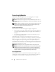
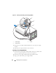
2
Slide the new system board into the open end of the blade chassis until the
retention latch or retention pin engages.
NOTE: Ensure that the system board plate is parallel with the chassis.
When the board assembly is installed correctly, the tabs on the system
board pan fit into the corresponding openings in the floor of the blade
chassis. See Figure 3-29 or Figure 3-30.
3
Reinstall the video daughter card or video riser card. See "Video
Controller" on page 145.