
Owners Manual


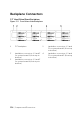


Table Of Contents
- About Your System
- Accessing System Features during Startup
- Front-Panel Features and Indicators
- Hard-Drive Indicator Patterns
- Service Tag
- Back Panel Features and Indicators
- System-Board Assembly Configurations
- LAN Indicator Codes
- Power and System Board Indicator Codes
- Power Supply Indicator Codes
- BMC Heart Beat LED
- Post Error Code
- System Event Log
- Sensor Data Record
- Other Information You May Need
- Using the System Setup Program
- Removing and Installing System Components
- Safety Instructions
- Recommended Tools
- Opening and Closing the System
- Inside the System
- Cooling Fans
- Hard Drives
- Removing a 3.5-inch Hard-Drive Blank
- Installing a 3.5-inch Hard-Drive Blank
- Removing a 2.5-inch Hard-Drive Blank
- Installing a 2.5-inch Hard-Drive Blank
- Removing a Hard-Drive Carrier
- Installing a Hard-Drive Carrier
- Removing a Hard Drive from a Hard-Drive Carrier
- Installing a Hard Drive into a Hard-Drive Carrier
- Installing a 2.5” SSD into a 3.5” Hard-Drive Carrier
- Power Supplies
- System-Board Assembly
- Air Baffle
- Heat Sinks
- Processors
- Interposer Extender for 2U Node
- Expansion-Card Assembly and Expansion Card
- PCI-E Slot Priority
- RAID Card
- LSI 9265-8i Card
- LSI 9265-8i RAID Battery
- Riser Card
- Optional Mezzanine Cards
- Removing the LSI 2008 SAS Mezzanine Card
- Installing the LSI 2008 SAS Mezzanine Card
- Cable Routing for LSI 2008 SAS Mezzanine Card (1U Node)
- Cable Routing for LSI 2008 SAS Mezzanine Card (2U Node)
- Removing the 1GbE Mezzanine Card
- Installing the 1GbE Mezzanine Card
- Removing the 10GbE Mezzanine Card
- Installing the 10GbE Mezzanine Card
- Mezzanine-Card Bridge Board
- System Memory
- System Battery
- System Board
- Power Distribution Boards
- Middle Planes
- Direct Backplanes
- 2.5-inch Hard Drive Expander Configuration
- Front Panels
- Sensor Boards
- Removing the Sensor Board for 3.5” Hard-Drive System
- Installing the Sensor Board for 3.5” Hard-Drive System
- Cable Routing for Sensor Board and Front Panel for 3.5” Hard Drive System
- Removing the Sensor Board for 2.5” Hard-Drive System
- Installing the Sensor Board for 2.5” Hard-Drive System
- Cable Routing for Sensor Board and Front Panel for 2.5” Hard Drive System
- Troubleshooting Your System
- Minimum Configuration to POST
- Safety First – For You and Your System
- Installation Problems
- Troubleshooting System Startup Failure
- Troubleshooting External Connections
- Troubleshooting the Video Subsystem
- Troubleshooting a USB Device
- Troubleshooting a Serial I/O Device
- Troubleshooting a NIC
- Troubleshooting a Wet System
- Troubleshooting a Damaged System
- Troubleshooting the System Battery
- Troubleshooting Power Supplies
- Troubleshooting System Cooling Problems
- Troubleshooting a Fan
- Troubleshooting System Memory
- Troubleshooting a Hard Drive
- Troubleshooting a Storage Controller
- Troubleshooting Expansion Cards
- Troubleshooting Processors
- IRQ Assignment Conflicts
- Jumpers and Connectors
- C6220 II System Board Connectors
- C6220 System Board Connectors
- Backplane Connectors
- Middle Plane Connectors
- Interposer Extender for 2U Node Connectors
- LSI 2008 SAS Mezzanine Card Connectors
- 1GbE Mezzanine Card Connectors
- 10GbE Mezzanine Card Connectors
- Power Distribution Board 1 Connectors
- Power Distribution Board 2 Connectors
- Sensor Board Connectors
- Jumper Settings
- Getting Help
- Index

5
Jumpers and Connectors | 331
Jumpers and Connectors
This chapter provides specific information about the system jumpers.
It also provides some basic information on jumpers and switches and
describes the connectors on the various boards in the system.
C6220 II System Board Connectors
Figure 5-1. C6220 II System Board Connectors
NOTE:
The internal USB connector is used for riser SD interface.
1
PCI-E Gen3 x8 mezzanine slot
3
2
Internal USB connector
3
NVRAM clear jumper
4
SGPIO in connector 2
5
onboard SATA output
connector 0
6
onboard SATA connector 4
7
onboard SATA connector 5
8
system battery
9
DIMM slots for processor 1
10
DIMM slots for processor 2
11
SAS/SATA input connector 5
12
middle plane connector
13
front panel connector 1
14
SAS/SATA input connector 0