
Service Manual


Memory Module Installation Guidelines
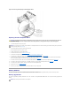
Starting with the connector nearest the side of the chassis, the memory module connectors are labeled "DIMM_1A" through "DIMM_3B" (see Figure4-29).
When you install memory modules, follow these guidelines:
l You must install memory modules in matched pairs.
l Install a pair of memory modules in connector DIMM_1A and DIMM_1B before installing a second pair in connectors DIMM_2A and DIMM_2B, and so on.
Figure 4-29. Memory Module Connectors
Table4-3 lists several sample memory configurations based on these guidelines.
Table 4-3. Sample Memory Module Configurations
Performing a Memory Upgrade
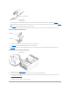
1. Open the bezel (see "Removing the Bezel").
2. Turn off the system, including any attached peripherals, and disconnect the system from the electrical outlet.
3. Remove the cover (see "Removing the Cover").
4. Remove the cooling shroud (see "Removing the Cooling Shroud").
5. Install or replace the memory module pairs as necessary to reach the desired memory total (see "Installing Memory Modules" and "Removing Memory
Modules").
See Figure4-29 to locate the memory module connectors.
6. Replace the cooling shroud (see "Replacing the Cooling Shroud").
7. Replace the cover (see "Replacing the Cover").
8. Reconnect the system to its electrical outlet and turn the system on, including any attached peripherals.
After the system completes the POST routine, it runs a memory test.
The system detects that the new memory does not match the system configuration information, which is stored in NVRAM. The monitor displays an error
message that ends with the following words:
Press <F1> to continue; <F2> to enter System Setup
Total Desired
Memory
Bank 1
Bank 2
Bank 3
A
B
C
D
E
F
256 MB
128 MB
128 MB
None
None
None
None
512 MB
256 MB
256 MB
None
None
None
None
1 GB
512 MB
512 MB
None
None
None
None
2 GB
512 MB
512 MB
512 MB
512 MB
None
None
3 GB
512 MB
512 MB
512 MB
512 MB
512 MB
512 MB
6 GB
1 GB
1 GB
1 GB
1 GB
1 GB
1 GB
CAUTION: Before you perform this procedure, you must turn off the system and disconnect it from its power source. For more information, see
the safety instructions in your System Information Guide.
CAUTION: Only trained service technicians are authorized to remove the system cover and access any of the components inside the system. See
your System Information Guide for complete information about safety precautions, working inside the computer, and protecting against
electrostatic discharge.