
Owners Manual


Table Of Contents
- OptiPlex 3050 Small Form Factor Owner's Manual
- Working on your computer
- Removing and installing components
- M.2 Intel Optane Memory Module 16 GB
- Technology and components
- System setup
- Software
- Troubleshooting your computer
- Technical specifications
- Contacting Dell
h bezel
i cover
7 Follow the procedure in After working inside your computer.
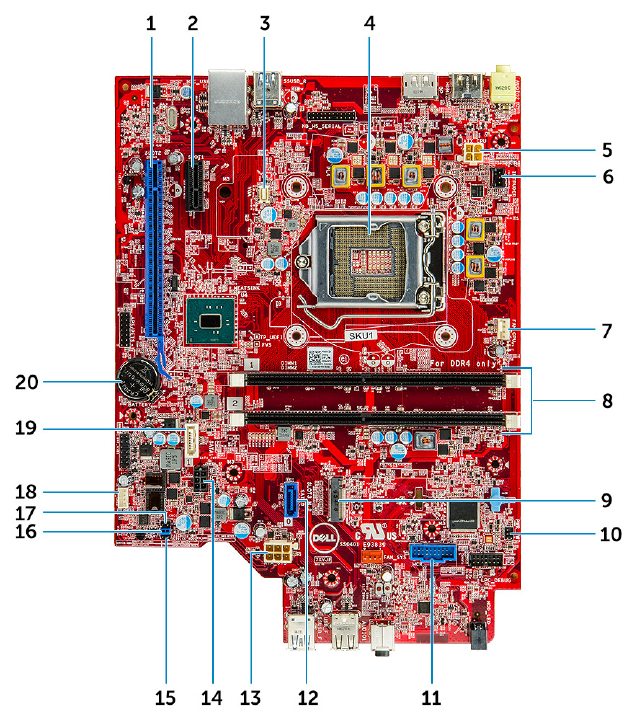
System board layout
1 PCI-e x16 connector (slot 2) 2 PCI-e x1 Connector (slot 1)
3 VGA daughter board connector 4 Processor connector (CPU)
5 CPU power connector (ATX_CPU) 6 Intrusion switch connector
7 CPU fan connector 8 Memory module connectors
9 M.2 Slot 3 connector 10 Power switch connector
11 SD Media card reader connector 12 SATA 0 connector
13 ATX power connector 14 HDD and ODD power cable connector
15 Service mode jumper 16 Clear password jumper
17 Clear CMOS jumper 18 Speaker connector
19 SATA 1 connector 20 Coin cell battery
32 Removing and installing components