
Service Manual


5. Lift the display panel a few inches from the display back cover.
6. Draw the LED ribbon-cable release tab away from the display back cover to release the ribbon cable, and lift the display panel fully from the display back
cover.
Removing the Display Panel Brackets
1. Follow the instructions in Before You Begin.
2. Remove the display assembly (see Display Assembly).
3. Remove the display bezel (see Removing the Display Bezel).
4. Remove the display panel (see Removing the Display Panel).
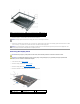
5. Remove the four M2 x 3-mm screws from each side of the display panel.
Removing the Display Panel Cable
1. Follow the instructions in Before You Begin.
2. Remove the display assembly (see Display Assembly).
3. Remove the display bezel (see Removing the Display Bezel).
4. Remove the display panel (see Removing the Display Panel).
5. Turn over the display panel, placing it on a clean surface.
6. Gently pull the pull tab on the bottom flex cable connector to release the cable from the inverter board.
CAUTION: To avoid damage to your display panel, handle the panel by the bracket tabs only.
CAUTION: Before you begin any of the procedures in this section, follow the safety instructions in the Product Information Guide.
CAUTION: To avoid electrostatic discharge, ground yourself by using a wrist grounding strap or by periodically touching an unpainted metal
surface, such as a connector on the back of the computer.
1
display
panel
2
display panel brackets (2) (left and right of
display panel)
3
M2 x 3-mm screws
(4)
CAUTION: Before you begin any of the procedures in this section, follow the safety instructions in the Product Information Guide.
CAUTION: To avoid electrostatic discharge, ground yourself by using a wrist grounding strap or by periodically touching an unpainted metal
surface, such as a connector on the back of the computer.
NOTICE: To avoid damage to the computer when replacing the bottom flex cable, gently support the bottom of the inverter board with one finger as
you reseat the bottom flex cable connector. Do not bend the inverter board.