
Owners Manual


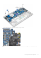


Table Of Contents
- Latitude 7490 Owner's Manual
- Contents
- Working on your computer
- Removing and installing components
- Recommended tools
- Screw size list
- Subscriber identification module card
- Base cover
- Battery
- Solid state drive
- Speaker
- Coin cell battery
- WWAN card
- WLAN card
- Memory modules
- Heat sink
- LED board
- Smart card module
- Touchpad buttons board
- Power connector port
- Display Assembly
- Touch display panel
- Display Bezel
- Nontouch display panel
- Camera Microphone Module
- Display Hinge Caps
- System board
- Keyboard
- Palm rest
- Technology and components
- System specifications
- System setup
- Boot menu
- Navigation keys
- System setup options
- General screen options
- System Configuration screen options
- Video screen options
- Security screen options
- Secure Boot screen options
- Intel software guard extensions screen options
- Performance screen options
- Power management screen options
- POST behavior screen options
- Manageability
- Virtualization support screen options
- Wireless screen options
- Maintenance screen options
- System logs screen options
- Admin and System password
- Updating the BIOS in Windows
- Software
- Troubleshooting
- Getting help and contacting Dell

1. Follow the procedure in Before working inside your computer.
2. Remove the base cover.
3. Disconnect the battery cable from the connector on the system board.
4. Remove the memory module.
5. Remove the PCIe SSD.
6. Remove the WLAN card.
7. Remove the WWAN card.
8. Remove the heat sink assembly.
9. Remove the system board.
10. Disconnect the cables from the palmrest end:
a. keyboard cable [1]
b. keyboard backlight cable [2] , USH Board cable(Optional)
c. Touchpad and USH board cables [3,4]
11. To remove the keyboard assembly:
NOTE: To identify the screws, see screw list
a. Remove the 18 (M2.0 x 2.5) screws that secure the keyboard [1].
b. Lift the keyboard assembly from the chassis [2].
Removing and installing components
45