
Owners Manual


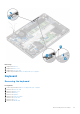


Table Of Contents
- Latitude 5300 Service Manual
- Contents
- Working on your computer
- Technology and components
- Major components of your system
- Disassembly and reassembly
- MicroSD card
- SIM card tray
- Base cover
- Battery
- WWAN card
- WLAN card
- Memory modules
- Solid-state drive
- Speakers
- System fan
- Heat sink
- DC-in port
- LED board
- Touchpad button board
- System board
- Coin-cell battery
- Display assembly
- Keyboard
- Keyboard bracket
- Smart card reader board
- Display bezel
- Hinge caps
- Display hinges
- Display panel
- Camera
- Display (eDP) cable
- Display back cover assembly
- Palmrest assembly
- Troubleshooting
- Getting help

Installing the display assembly
About this task
NOTE:
Ensure that the hinges are opened to the maximum before replacing the display assembly on the palmrest and
keyboard assembly.
Steps
1. Align and place the system chassis under the hinges of the display assembly [1].
2. Replace the four (M2.5x3) screws that secure the display assembly to the system chassis [2].
84
Disassembly and reassembly