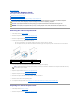
Dell™ Inspiron™ 535s/537s/545s/546s Service Manual Technical Overview Before You Begin Computer Cover Support Bracket Front Bezel Memory PCI and PCI Express Cards Drives Fans Front I/O Panel Processor System Board Power Supply Battery System Setup Models DCSLE and DCSLF Notes, Cautions, and Warnings NOTE: A NOTE indicates important information that helps you make better use of your computer. CAUTION: A CAUTION indicates potential damage to hardware or loss of data if instructions are not followed.
Back to Contents Page Before You Begin Dell™ Inspiron™ 535s/537s/545s/546s Service Manual Technical Specifications Recommended Tools Turning Off Your Computer Safety Instructions This chapter provides procedures for removing and installing the components in your computer. Unless otherwise noted, each procedure assumes that the following conditions exist: l You have performed the steps in Turning Off Your Computer and Safety Instructions.
. Disconnect all telephone or network cables from the computer. 4. Disconnect your computer and all attached devices from their electrical outlets. 5. Press and hold the power button while the system is unplugged to ground the system board. CAUTION: Before touching anything inside your computer, ground yourself by touching an unpainted metal surface, such as the metal at the back of the computer.
Back to Contents Page Front Bezel Dell™ Inspiron™ 535s/537s/545s/546s Service Manual Removing the Front Bezel Replacing the Front Bezel WARNING: Before working inside your computer, read the safety information that shipped with your computer. For additional safety best practices information, see the Regulatory Compliance Homepage at www.dell.com/regulatory_compliance. WARNING: To guard against electrical shock, always unplug your computer from the electrical outlet before removing the cover.
Back to Contents Page Support Bracket Dell™ Inspiron™ 535s/537s/545s/546s Service Manual Removing the Support Bracket Replacing the Support Bracket WARNING: Before working inside your computer, read the safety information that shipped with your computer. For additional safety best practices information, see the Regulatory Compliance Homepage at www.dell.com/regulatory_compliance. WARNING: To guard against electrical shock, always unplug your computer from the electrical outlet before removing the cover.
1 screw 2 card retention bracket 3 support bracket insert tab 4 hinge tab 5 hinge 6 support bracket Replacing the Support Bracket Inspiron 535s/537s 1. Align and insert the hinges at the bottom of the support bracket into the hinge tabs located along the edge of the computer. 2. Pull back the support bracket release latch and pivot the support bracket downward, until the support bracket release latch locks into place. 3. Replace the computer cover (see Replacing the Computer Cover).
Back to Contents Page PCI and PCI Express Cards Dell™ Inspiron™ 535s/537s/545s/546s Service Manual Removing PCI and PCI Express Cards Replacing PCI and PCI Express Cards Configuring Your Computer After Removing or Installing a PCI/PCI Express Card WARNING: Before working inside your computer, read the safety information that shipped with your computer. For additional safety best practices information, see the Regulatory Compliance Homepage at www.dell.com/regulatory_compliance.
3. 4. Remove the support bracket (see Removing the Support Bracket). Prepare the card for installation. See the documentation that came with the card for information on configuring the card, making internal connections, or otherwise customizing it for your computer. 5. If you are installing the PCI Express card into the x16 card connector, position the card so the securing slot is aligned with the securing tab.
Card 2. 3. Network Card 1. 2. 3. Entering System Setup). Go to Onboard Audio Controller and then change the setting to Disabled. Connect the external audio devices to the sound card's connectors. Enter system setup (see Entering System Setup) Go to Onboard LAN Controller and then change the setting to Disabled. Connect the network cable to the network card's connector. Back to Contents Page 2. 3. 1. 2. 3. Entering System Setup).
Back to Contents Page Battery Dell™ Inspiron™ 535s/537s/545s/546s Service Manual Removing the Battery Replacing the Battery WARNING: Before working inside your computer, read the safety information that shipped with your computer. For additional safety best practices information, see the Regulatory Compliance Homepage at www.dell.com/regulatory_compliance. WARNING: A new battery can explode if it is incorrectly installed.
Back to Contents Page
Back to Contents Page Computer Cover Dell™ Inspiron™ 535s/537s/545s/546s Service Manual Removing the Computer Cover Replacing the Computer Cover WARNING: Before working inside your computer, read the safety information that shipped with your computer. For additional safety best practices information, see the Regulatory Compliance Homepage at www.dell.com/regulatory_compliance. WARNING: To guard against electrical shock, always unplug your computer from the electrical outlet before removing the cover.
Replacing the Computer Cover 1. Ensure that all cables are connected, and fold cables out of the way. 2. Ensure that no tools or extra parts are left inside the computer. 3. Align the tabs at the bottom of the computer cover with the slots located along the edge of the computer. 4. Press the computer cover down and slide it towards the front of the computer until you feel a click or feel the computer cover securely installed. 5. Ensure that the cover is seated correctly. 6.
Back to Contents Page Processor Dell™ Inspiron™ 535s/537s/545s/546s Service Manual Removing the Processor Replacing the Processor WARNING: Before working inside your computer, read the safety information that shipped with your computer. For additional safety best practices information, see the Regulatory Compliance Homepage at www.dell.com/regulatory_compliance. WARNING: To guard against electrical shock, always unplug your computer from the electrical outlet before removing the cover.
1 processor 2 release lever 3 socket CAUTION: When removing the processor, do not touch any of the pins inside the socket or allow any objects to fall on the pins in the socket. 6. Gently lift the processor to remove it from the socket. Leave the release lever extended in the release position so that the socket is ready for the new processor. Replacing the Processor CAUTION: Ground yourself by touching an unpainted metal surface on the back of the computer.
1 front alignment notch 2 processor pin-1 indicator 3 rear alignment notch 4 processor cover 5 center cover latch 6 processor 7 socket 8 tab 9 release lever Inspiron 546s 1 socket 2 processor pin-1 indicator 3 processor 4 release lever 4. For Inspiron 535s/537s/545s, orient the front and rear alignment-notches on the processor with the front and rear alignment-notches on the socket. 5. Align the pin-1 corners of the processor and socket.
12. Replace the computer cover (see Replacing the Computer Cover).
Back to Contents Page Drives Dell™ Inspiron™ 535s/537s/545s/546s Service Manual Removing a Hard Drive Replacing a Hard Drive Removing a Media Card Reader Replacing a Media Card Reader Removing an Optical Drive Replacing an Optical Drive WARNING: Before working inside your computer, read the safety information that shipped with your computer. For additional safety best practices information, see the Regulatory Compliance Homepage at www.dell.com/regulatory_compliance.
a. Pull the securing tab upwards and slide the hard drive out and up. 1 securing tab 2 power cable 4 hard drive 3 data cable 5 shoulder screws (4) 6. Replace the support bracket (see Replacing the Support Bracket). 7. Replace the computer cover (see Replacing the Computer Cover). 8. Connect the computer and other devices to an electrical outlet. 9. If removing the hard drive changes the drive configuration, ensure that you reflect these changes in system setup (see System Setup).
Removing a Media Card Reader 1. Follow the procedures in Before You Begin. 2. Remove the computer cover (see Removing the Computer Cover). 3. Remove the front bezel (see Removing the Front Bezel). 4. Disconnect the FlexBay USB cable and the power cable from the back of the media card reader. NOTE: If you are not replacing the media card reader at this time, disconnect the other end of the FlexBay USB cable from the system board and set it aside.
8. Connect your computer and devices to electrical outlets, and then turn them on. Replacing a Media Card Reader 1. Follow the procedures in Before You Begin. 2. Remove the computer cover (see Removing the Computer Cover). 3. Remove the front bezel (see Removing the Front Bezel). 4. If this is a new media card reader installation, remove the break-away metal plate.
Removing an Optical Drive 1. Follow the procedures in Before You Begin. 2. Remove the computer cover (see Removing the Computer Cover). 3. Remove the front bezel (see Removing the Front Bezel). 4. Disconnect the power cable and the data cable from the back of the optical drive. NOTE: If you are not replacing the optical drive at this time, disconnect the other end of the data cable from the system board and set it aside. You can use the data cable to install an optical drive at a later time. 5.
1 data cable 2 power cable 3 securing tab 4 shoulder screws (2) 5 optical drive 6. Replace the front bezel (see Replacing the Front Bezel). 7. Replace the computer cover (see Replacing the Computer Cover). 8. Connect your computer and devices to electrical outlets, and then turn them on. 9. Configure the drives in system setup (see System Setup Options). Replacing an Optical Drive 1. Follow the procedures in Before You Begin. 2. Remove the computer cover (see Removing the Computer Cover). 3.
Back to Contents Page Fans Dell™ Inspiron™ 535s/537s/545s/546s Service Manual Removing the Processor Fan and Heat Sink Assembly Replacing the Processor Fan and Heat Sink Assembly Removing the Chassis Fan Replacing the Chassis Fan WARNING: Before working inside your computer, read the safety information that shipped with your computer. For additional safety best practices information, see the Regulatory Compliance Homepage at www.dell.com/regulatory_compliance.
Inspiron 546s a. b. Rotate the clamp lever 180 degrees counter-clockwise to release the clamp grip from the bracket projection. Rotate the processor fan and heat sink assembly upward gently, and remove it from the computer. Lay the processor fan and heat sink assembly down on its top, with the thermal grease facing upward.
1 processor fan and heat sink assembly 2 clamp lever 3 bracket projection 4 clamp grip 5 bracket 4. Connect the processor fan and heat sink assembly cable to the fan connector on the system board (see System Board Components). 5. Replace the computer cover (see Replacing the Computer Cover). 6. Connect your computer and devices to an electrical outlet, and turn them on. Removing the Chassis Fan CAUTION: Do not touch the fan blades when you are removing the chassis fan. This could damage the fan. 1.
1 screw 2 chassis fan Replacing the Chassis Fan 1. Follow the procedures in Before You Begin. 2. Align the top and bottom chassis fan tabs with the projections in the chassis, and slide the chassis fan towards the back of the computer. 1 bottom tab 2 top tabs (2) 3 screw 3. Replace the screw that secures the chassis fan. 4. Connect the chassis fan cable to the chassis fan connector on the system board (see System Board Components). 5. Replace the computer cover (see Replacing the Computer Cover).
Back to Contents Page Front I/O Panel Dell™ Inspiron™ 535s/537s/545s/546s Service Manual Removing the Front I/O Panel Replacing the Front I/O Panel WARNING: Before working inside your computer, read the safety information that shipped with your computer. For additional safety best practices information, see the Regulatory Compliance Homepage at www.dell.com/regulatory_compliance. WARNING: To guard against electrical shock, always unplug your computer from the electrical outlet before removing the cover.
1. Align and slide the I/O panel into the I/O panel clamp slot. 2. Replace the screw that secures the I/O panel to the chassis. 3. Connect the cables to the system board connectors. 4. Replace the hard drive (see Replacing a Hard Drive). 5. Replace the support bracket (see Replacing the Support Bracket). 6. Replace the front bezel (see Replacing the Front Bezel). 7. Replace the computer cover (see Replacing the Computer Cover). 8.
Back to Contents Page Memory Dell™ Inspiron™ 535s/537s/545s/546s Service Manual Removing Memory Replacing Memory Recommended Memory Configuration Setting Up Dual Channel Memory Configuration WARNING: Before working inside your computer, read the safety information that shipped with your computer. For additional safety best practices information, see the Regulatory Compliance Homepage at www.dell.com/regulatory_compliance.
3 notch 4 memory module CAUTION: To avoid damage to the memory module, press the memory module straight down into the connector while you apply equal force to each end of the memory module. 5. Insert the memory module into the connector until the memory module snaps into position. If you insert the memory module correctly, the securing clips snap into the cutouts at each end of the memory module. 1 cutouts (2) 2 securing clip (snapped in position) 6.
1 Pair A: matched pair of memory modules in connectors DIMM1 and DIMM3 2 Pair B: matched pair of memory modules in connectors DIMM2 and DIMM4 Inspiron 546s 1 Pair B: matched pair of memory modules in connectors DIMM3 and DIMM4 Back to Contents Page 2 Pair A: matched pair of memory modules in connectors DIMM1 and DIMM2
Back to Contents Page Power Supply Dell™ Inspiron™ 535s/537s/545s/546s Service Manual Removing the Power Supply Replacing the Power Supply WARNING: Before working inside your computer, read the safety information that shipped with your computer. For additional safety best practices information, see the Regulatory Compliance Homepage on www.dell.com at the following location: www.dell.com/regulatory_compliance.
2. Replace the three screws that secure the power supply to the computer chassis. NOTE: Route the DC power cables under the chassis tabs. The cables must be properly routed to prevent the cables from being damaged. 3. Connect the DC power cables to the system board and drives. 4. Secure all the cables to the securing clip on the side of the power supply. NOTE: Double-check all cable connections to make sure they are secure. 5. Replace the support bracket (see Replacing the Support Bracket). 6.
Back to Contents Page System Setup Dell™ Inspiron™ 535s/537s/545s/546s Service Manual Overview Entering System Setup Clearing Forgotten Passwords Clearing CMOS Settings Flashing the BIOS Overview Use System Setup: l To change the system configuration information after you add, change, or remove any hardware in your computer. l To set or change a user-selectable option such as the user password. l To read the current amount of memory or set the type of hard drive installed.
Cache Memory Installed Indicates the amount of installed memory. Memory Available Indicates the amount of available memory. Memory Speed Indicates the frequency of installed memory. Memory Channel Mode Indicates the channel mode of installed memory. System Memory Type Indicates the type of installed memory. Standard CMOS Features Date Displays current date in the format (mm:dd:yyyy). Time Displays current time in the format (hh:mm:ss).
ACPI Suspend Type S1(POS); S3(STR) (S3(STR) by default). Remote Wake Up On; Off (On by default) Auto Power On Enabled; Disabled (Disabled by default). Auto Power On Date 0 Auto Power On Time 0:00:00 AC Recovery Off; On; Last (Off by default). Set Supervisor Password Supervisor Password Installed; Not Installed (Not Installed by default). Change Supervisor Password Press Enter to change the supervisor password.
Video Memory Size 1 MB, 8 MB (8 MB by default). DVMT Mode FIXED, DVMT (DVMT by default). DVMT/FIXED Memory Size 128 MB, 256 MB, MAX (128 MB by default). Integrated Peripherals USB Device Setting l l USB Controller—Enabled or Disabled (Enabled by default). USB Operation Mode—High Speed; Full/Low Speed (High Speed by default). Onboard AUDIO Controller Enabled or Disabled (Enabled by default). Onboard LAN Controller Enabled or Disabled (Enabled by default).
CPU Feature l l l USB Device Setting l l AMD Virtualization—Enabled; Disabled (Enabled by default). AMD Cool 'N' Quiet Function—Enabled; Disabled (Enabled by default). AMD Live!—indicates the AMD Live! status. USB Controller—Enabled or Disabled (Enabled by default). USB Operation Mode—High Speed; Full/Low Speed (High Speed by default). Advanced Chipset Features Init Display First PCI-E 16X Slot; PCI-E 1X Slot; PCI Slot; Onboard (PCI-E 16X Slot by default).
4. At the bottom of the menu, enter the number of the device that is to be used for the current boot only. For example, if you are booting to a USB memory key, highlight USB Flash Device and press . NOTE: To boot to a USB device, the device must be bootable. To make sure your device is bootable, check the device documentation. Changing Boot Sequence for Future Boots 1. Enter system setup (see Entering System Setup). 2.
Inspiron 546s 4. Remove the 2-pin jumper plug from pins 2 and 3 and fix it on pins 1 and 2. 5. Turn on the computer, wait for approximately five seconds, and then turn off the computer. If required, press and hold the power button to turn off the computer. 6. Remove the 2-pin jumper plug from pins 1 and 2 and replace it on pins 2 and 3 to enable the password feature. 7. Replace the computer cover (see Replacing the Computer Cover). 8.
Inspiron 535s/537s Inspiron 545s Inspiron 546s 4. Replace the computer cover (see Replacing the Computer Cover).
5. Connect your computer and devices to electrical outlets, and turn them on. Flashing the BIOS The BIOS may require flashing when an update is available or when replacing the system board. 1. Turn on the computer. 2. Locate the BIOS update file for your computer at the Dell Support website at support.dell.com. 3. Click Download Now to download the file. 4. If the Export Compliance Disclaimer window appears, click Yes, I Accept this Agreement. The File Download window appears. 5.
Back to Contents Page System Board Dell™ Inspiron™ 535s/537s/545s/546s Service Manual Removing the System Board Replacing the System Board WARNING: Before working inside your computer, read the safety information that shipped with your computer. For additional safety best practices information, see the Regulatory Compliance Homepage at www.dell.com/regulatory_compliance. WARNING: To guard against electrical shock, always unplug your computer from the electrical outlet before removing the cover.
1 screws (8) 2 system board Compare the system board that you just removed with the replacement system board to ensure that they are identical. Replacing the System Board 1. Gently align the system board into the chassis and slide it towards the back of the computer. CAUTION: Ensure that the port retention springs are not damaged while replacing the sytem board.
2. Replace the screws that secure the system board to the chassis. 3. Connect the cables that you removed from the system board. CAUTION: Ensure that the processor fan and heat sink assembly is correctly seated and secure. 4. Replace the processor (see Replacing the Processor). 5. Replace the processor fan and the heat sink assembly (see Replacing the Processor Fan and Heat Sink Assembly). 6.
Back to Contents Page Technical Overview Dell™ Inspiron™ 535s/537s/545s/546s Service Manual Inside View of Your Computer System Board Components WARNING: Before working inside your computer, read the safety information that shipped with your computer. For additional safety best practices information, see the Regulatory Compliance Homepage at www.dell.com/regulatory_compliance.
(FAN_CPU) (DIMM1) 5 memory module connector (DIMM2) 6 password reset jumper (CLR_PSW) 7 main power connector (ATX1_POWER1) 8 SATA connector (SATA_1) 9 SATA connector (SATA_0) 10 front panel connector (FRONTPANEL) 11 CMOS reset jumper (CLR_CMOS) 12 front panel USB connector (F_USB2) 13 front panel USB connector (F_USB1) 14 front panel audio (FP_AUDIO) 15 PCI card slot (PCI_2) 16 PCI card slot (PCI_1) 17 battery socket (BATTERY) 18 PCI-Express x1 card slot (PCIEX1) 19 PCI-Express x16 card
1 12 V power connector (PWR2) 2 processor socket 3 processor fan connector (CPU_FAN1) 4 memory module connector (DIMM4) 5 memory module connector (DIMM3) 6 memory module connector (DIMM2) 7 memory module connector (DIMM1) 8 password reset jumper (PSWD1) 9 main power connector (PWR1) 10 battery socket (BAT1) 11 CMOS reset jumper (CLR_CMOS1) 12 front panel connector (FP1) 13 SATA connector (SATA_2) 14 SATA connector (SATA_1) 15 SATA connector (SATA_0) 16 SATA connector (SATA_3) 17 front