
User's Manual

Troubleshooting and Recovery 411
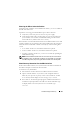
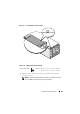
Observing the LEDs to Isolate the Problem
Facing the front of CMC as it is installed in the chassis, you see two LEDs on
the left side of the card.
Top LED — The top green LED indicates power. If it is NOT on:
1
Verify that you have AC present to at least one power supply.
2
Verify that the CMC card is seated properly. You can release/pull on the
ejector handle, remove CMC, reinstall CMC making sure the board is
inserted all the way and the latch closes correctly.
Bottom LED — The bottom LED is multi-colored. When CMC is active and
running, and there are no problems, the bottom LED is blue. If it is amber, a
fault was detected. The fault could be caused by any of the following three
events:
• A core failure. In this case, the CMC board must be replaced.
• A self-test failure. In this case, the CMC board must be replaced.
• An image corruption. In this case, you can recover CMC by uploading the
CMC firmware image.
NOTE: A normal CMC boot/reset takes over a minute to fully boot into its OS and
be available for login. The blue LED is enabled on the active CMC. In a redundant,
two-CMC configuration, only the top green LED is enabled on the standby CMC.
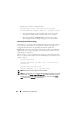
Obtain Recovery Information From the DB-9 Serial Port
If the bottom LED is amber, recovery information should be available from
the DB-9 serial port located on the front of CMC.
To obtain recovery information:
1
Install a NULL modem cable between CMC and a client machine.
2
Open a terminal emulator of your choice (such as HyperTerminal or
Minicom). Set up: 8 bits, no parity, no flow control, baud rate 115200.
A core memory failure displays an error message every 5 seconds.
3
Press <Enter>. If a
recovery
prompt appears, additional information is
available. The prompt indicates the CMC slot number and failure type.
To display failure reason and syntax for a few commands, type
recover