Dell Latitude 14 Rugged — 5404 Owner's Manual Regulatory Model: P46G Regulatory Type: P46G001
Notes, Cautions, and Warnings NOTE: A NOTE indicates important information that helps you make better use of your computer. CAUTION: A CAUTION indicates either potential damage to hardware or loss of data and tells you how to avoid the problem. WARNING: A WARNING indicates a potential for property damage, personal injury, or death. Copyright © 2014 Dell Inc. All rights reserved. This product is protected by U.S. and international copyright and intellectual property laws.
Contents 1 Working on Your Computer................................................................................5 Before Working Inside Your Computer................................................................................................ 5 Turning Off Your Computer..................................................................................................................6 After Working Inside Your Computer......................................................................................
Removing the Display Assembly.........................................................................................................24 Installing the Display Assembly...........................................................................................................25 Removing the I/O Board.....................................................................................................................26 Installing the I/O Board....................................................................
Working on Your Computer 1 Before Working Inside Your Computer Use the following safety guidelines to help protect your computer from potential damage and to help to ensure your personal safety. Unless otherwise noted, each procedure included in this document assumes that the following conditions exist: • You have read the safety information that shipped with your computer. • A component can be replaced or--if purchased separately--installed by performing the removal procedure in reverse order.
3. If the computer is connected to a docking device (docked), undock it. CAUTION: To disconnect a network cable, first unplug the cable from your computer and then unplug the cable from the network device. 4. Disconnect all network cables from the computer. 5. Disconnect your computer and all attached devices from their electrical outlets. 6. Close the display and turn the computer upside-down on a flat work surface.
2. 2. Click the arrow in the lower-right corner of the Start menu as shown below, and then click Shut Down . Ensure that the computer and all attached devices are turned off. If your computer and attached devices did not automatically turn off when you shut down your operating system, press and hold the power button for about 6 seconds to turn them off.
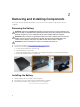
Removing and Installing Components 2 This section provides detailed information on how to remove or install the components from your computer. Removing the Battery WARNING: Using an incompatible battery may increase the risk of fire or explosion. Replace the battery only with a compatible battery purchased from Dell. The battery is designed to work with your Dell computer. Do not use a battery from any other computer with your computer.
Removing the Hard Drive 1. Follow the procedures in Before Working Inside Your Computer 2. Remove: a. Battery 3. Perform the following steps as shown in the illustration: a. Unlock the hard-drive press latch door [1]. b. Lift it upwards to open it [2]. c. Push and hold the hard drive release button to the left while pulling on the plastic hard drive tab [3]. d. Remove the hard drive from the computer [4]. Installing the Hard Drive 1. Slide the hard drive into its place on the computer. 2.
Installing the Optical Drive 1. Place the optical drive on to the computer. 2. Tighten the screws that secure the optical drive to the computer. 3. Install: a. Hard Drive b. Battery 4. Follow the procedures in After Working Inside Your computer Removing the Bottom Cover 1. Follow the procedures in Before Working Inside Your Computer 2. Remove: a. Battery b. Hard Drive c. Optical Drive 3. Perform the following steps as shown in the illustration: a. Unlock the I/O latch door [1]. b.
4. Perform the following steps as shown in the illustration: a. Unlock back door latch [1]. b. Lift the back door upward direction to open it [2]. c. Remove the screws that secure the bottom cover to the computer chassis [3]. 5. Perform the following steps as shown in the illustration: a. Unlock the HDMI latch door [1]. b. Lift the latch door upward direction [2]. c. Remove the screw that secure the bottom cover to the computer chassis [3]. 6.
Installing the Bottom Cover 1. Tighten the screws that secure I/O, back door, and HDMI to the computer chassis. 2. Press firmly on the door until a click is heard and latch is engaged. 3. Place the bottom cover on the base of the computer. 4. Tighten the screws that secure the bottom cover to the computer chassis. 5. Install: a. Optical Drive b. Hard Drive c. Battery 6. Follow the procedures in After Working Inside Your computer Removing the Keyboard 1.
4. Perform the following steps as shown in the illustration: a. Remove the screws that secure the keyboard door [1]. b. Lift the locking tab [2]. c. Disconnect the keyboard cables from the system board [3]. 5. Lift and remove the keyboard from the computer chassis Installing the Keyboard 1. Connect the keyboard cables to its connectors on the keyboard controller card. 2. Place the keyboard door over its slot on the computer chassis. 3.
a. Battery 7. Follow the procedures in After Working Inside Your computer Removing the Memory Module 1. Follow the procedures in Before Working Inside Your Computer 2. Remove: a. b. c. d. Battery Hard Drive Optical Drive Bottom Cover 3. Pry the securing clips away from the memory module until it pops up 4. Remove the memory module from its connector on the system board. Installing the Memory Module 1. Insert the memory module into the memory socket. 2.
b. c. d. e. f. 4. Unroute the antenna cables [2]. Remove the screws that secure the docking board [3]. Flip the docking board [4]. Lift the release tab [5]. Disconnect the docking board connector cable from the system board [6]. Lift and remove the docking board from the computer chassis. Installing the Docking Board 1. Connect the docking board connector cable to the system board. 2. Flip the docking board and seat it on the slot. 3. Tighten the screws to secure the docking board. 4.
c. Remove the screws that secure the pull tab to the GPU board [3]. d. Lift the GPU board from the computer [4]. Installing the GPU Board 1. Place the GPU board on the computer. 2. Tighten the screws that secure the pull tab to the GPU board. 3. Place the GPU socket on the board. 4. Tighten the screws that secure the socket to the computer. 5. Install: a. b. c. d. e. 6.
Installing the SIM Module 1. Slide the SIM module into its place on the computer. 2. Close the SIM module bay press latch door. 3. Tighten the screws that secure the module to the computer. 4. Connect the cable. 5. Press the locking tab. 6. Install: a. b. c. d. 7. Bottom Cover Optical Drive Hard Drive Battery Follow the procedures in After Working Inside Your computer Removing the WLAN Card 1. Follow the procedures in Before Working Inside Your Computer 2. Remove: a. b. c. d. e. 3.
Installing the WLAN Card 1. Insert the WLAN card in the slot. 2. Connect the screw to secure the cable holder. 3. Connect the antenna cables to the WLAN card. 4. Install: a. b. c. d. e. 5. GPS Holder Bottom Cover Optical Drive Hard Drive Battery Follow the procedures in After Working Inside Your computer Removing the WWAN Card 1. Follow the procedures in Before Working Inside Your Computer 2. Remove: a. b. c. d. e. 3.
Installing the WWAN Card 1. Insert the WWAN card in the slot. 2. Connect the screw to secure the WWAN. 3. Connect the cables to the WWAN card. 4. Install: a. b. c. d. e. 5. GPS Holder Bottom Cover Optical Drive Hard Drive Battery Follow the procedures in After Working Inside Your computer Removing the GPS Holder 1. Follow the procedures in Before Working Inside Your Computer 2. Remove: a. b. c. d. 3.
Installing the RF Holder 1. Place the RF holder into its place on the computer. 2. Tighten the screw that secure the holder to the computer. 3. Connect the antenna cable. 4. Align the cable to the computer. 5. Install: a. b. c. d. e. f. g. 6. Docking Board WLAN Card GPS Holder Bottom Cover Optical Drive Hard Drive Battery Follow the procedures in After Working Inside Your computer Removing the Heatsink 1. Follow the procedures in Before Working Inside Your Computer 2. Remove: a. b. c. d. e.
Installing the Heatsink 1. Align the heatsink to its position on the system board. 2. Tighten the screws in the numerical sequence depicted on the bracket, to secure the heatsink on the system board. 3. Install: a. b. c. d. e. f. g. 4. SIM Module GPU Board Docking Board Bottom Cover Optical Drive Hard Drive Battery Follow the procedures in After Working Inside Your computer Removing the System Fan 1. Follow the procedures in Before Working Inside Your Computer 2. Remove: a. b. c. d. 3.
a. b. c. d. 6. Bottom Cover Optical Drive Hard Drive Battery Follow the procedures in After Working Inside Your computer Removing the RF Holder 1. Follow the procedures in Before Working Inside Your Computer 2. Remove: a. b. c. d. e. f. g. 3. Battery Hard Drive Optical Drive Bottom Cover GPS Holder WLAN Card Docking Board Perform the following steps as shown in the illustration: a. b. c. d. Flip the antenna cables [1]. Disconnect the antenna cables [2].
b. c. d. e. f. 6. WWAN Card Bottom Cover Optical Drive Hard Drive Battery Follow the procedures in After Working Inside Your computer Removing the GPS Holder 1. Follow the procedures in Before Working Inside Your Computer 2. Remove: a. b. c. d. 3. Battery Hard Drive Optical Drive Bottom Cover Perform the following steps as shown in the illustration: a. Unroute the antenna cable [1]. b. Remove the screw that secure the GPS holder to the computer [2]. c. Lift the holder from the computer [3].
e. Optical Drive f. Hard Drive g. Battery 6. Follow the procedures in After Working Inside Your computer Removing the Display Assembly 1. Follow the procedures in Before Working Inside Your Computer 2. Remove: a. Battery b. Hard Drive c. Optical Drive d. Bottom Cover 3. Perform the following steps as shown in the illustration: a. Lift the locking tab [1]. b. Disconnect the I/O cable [2]. c. Peel the adhesive tape [3]. d. Disconnect the eDP cable on the system board [4]. e.
5. Remove the screws that secure the display assembly to the computer chassis. 6. Flip the computer remove the display assembly. Installing the Display Assembly 1. Install the display assembly and close the display. 2. Flip the computer chassis. 3. Tighten the screws that secure that display assembly to the computer chassis. 4. Connect the display assembly connector 5. Place the tab. 6. Tighten the screws that secure that secure display assembly connector. 7.
Removing the I/O Board 1. Follow the procedures in Before Working Inside Your Computer 2. Remove: a. b. c. d. 3. Battery Hard Drive Optical Drive Bottom Cover Perform the following steps as shown in the illustration: a. Unlock the I/O press latch door [1]. b. Lift it upwards to open it [2]. c. Remove the screw that secures I/O board to the computer chassis [3]. 4. Perform the following steps as shown in the illustration: a. b. c. d. 5. Lift the locking tab [1].
Installing the I/O Board 1. Place the I/O board on the computer. 2. Tighten the scews that secure the I/O board to the computer. 3. Connect display assembly cable to the computer. 4. Connect the I/O cable to the computer 5. Tighten the screw that secures the I/O board. 6. Slide the I/O into its place on the computer. 7. Close the I/O bay press the latch door. 8. Install: a. b. c. d. 9.
d. Lift the tab upwards direction [4]. e. Lift the locking tab [1]. f. Disconnect the optical drive connector cable from the system board [2]. 4. Remove the ODD connector from the computer. Installing the Optical Drive Connector 1. Place the optical drive on to the computer. 2. Connect the optical drive connector cable. 3. Press the locking tab 4. Tighten the screws that secure the optical drive to the computer. 5. Flip the optical drive connector and seat it on the slot. 6.
Installing the Storage Connector 1. Place the storage connector on the computer. 2. Tighten the screws that secure the storage connector 3. Connect the storage connector cable to the computer. 4. Install: a. b. c. d. 5. Bottom Cover Optical Drive Hard Drive Battery Follow the procedures in After Working Inside Your computer Removing the SSD Bracket 1. Follow the procedures in Before Working Inside Your Computer 2. Remove: a. b. c. d. 3.
4. Perform the following steps as shown in the illustration: a. Remove the screws that secure the SSD bracket to the computer [1]. b. Lift the SSD bracket from the computer [2]. Installing the SSD Bracket 1. Place the SSD bracket on the computer. 2. Tighten the screws that secure the SSD connector 3. Affix the adhesive tape to the computer 4. Connect the SSD braket cable to the computer. 5. Install: a. b. c. d. 6.
c. Optical Drive d. Bottom Cover 3. Perform the following steps as shown in the illustration: a. b. c. d. e. f. 4. Lift the locking tab [1]. Disconnect the USH board cables from the connectors [2]. Remove the screws that secure the board [3]. Lift and flip the board at an angle to access the smart card cable at the bottom [4]. Lift the locking tab [5]. Disconnect the smart card cable and release the USH board from the computer chassis [6]. Remove the USH board from the computer.
e. Remove the screws that secure the driving board to the computer [5] f. Lift the driving board from the computer [6]. Installing the Driving Board 1. Place the driving board on the computer. 2. Tighten the screws that secure the driving board on the computer. 3. Connect the I/O board cable. 4. Affix the adhesive tape. 5. Connect the display assembly cable 6. Affix the tape. 7. Install: a. b. c. d. 8.
Installing the Battery Connector 1. Place the battery connector on the system board.. 2. Tighten the screws that secure the battery connector to the computer. 3. Connect the battery connector cable. 4. Install: a. b. c. d. e. 5. I/O Board Bottom Cover Optical Drive Hard Drive Battery Follow the procedures in After Working Inside Your computer Removing the System Board 1. Follow the procedures in Before Working Inside Your Computer 2. Remove: a. b. c. d. e. f. g. h. 3.
4. Perform the following steps as shown in the illustration: a. Unlock the latch door[1]. b. Lift it downwards to open it [2]. c. Remove the screws that secure to the system board. 5. Perform the following steps as shown in the illustration: a. Remove the screws that secure the system board to the computer [1]. b. Lift the system board from the computer [2].
Installing the System Board 1. Place the system board on the computer. 2. Tighten the screws that secure the system board to the computer. 3. Connect the mother board cable to the computer 4. Tighten the screws that secure the connector to the computer chassis. 5. Slide the drive into its place on the computer. 6. Close the drive bay. 7. Install: a. b. c. d. e. f. g. 8.
System Setup 3 System Setup enables you to manage your computer hardware and specify BIOS‐level options.
Table 1. Navigation Keys Keys Navigation Up arrow Moves to the previous field. Down arrow Moves to the next field. Allows you to select a value in the selected field (if applicable) or follow the link in the field. Spacebar Expands or collapses a drop‐down list, if applicable. Moves to the next focus area. NOTE: For the standard graphics browser only. Moves to the previous page till you view the main screen.
Option Description By default, all the options are checked. You can also deselect any option or change the boot order. Boot List Option Allows you to change the boot list option. • • Legacy (Enabled) UEFI Advanced Boot Options This option allows you the legacy option ROMs to load. By default, the Enable Legacy Option ROMs is checked. Date/Time Allows you to change the date and time. Table 3.
Option Description • Drives Allows you to configure the SATA drives on board. All drives are enabled by default. The options are: • • • • SMART Reporting SATA-0 SATA-1 SATA-2 SATA-3 This field controls whether hard drive errors for integrated drives are reported during system startup. This technology is part of the SMART (Self Monitoring Analysis and Reporting Technology) specification. This option is disabled by default. • USB Configuration RAID On: This option is enabled by default.
Option Description RGB Keyboard Backlight This option configures the RGB keyboard backlight feature. There are six available colors: four preset colors (white, red, green, and blue) and two user configurable colors. Touchscreen This field controls whether the touchscreen is enabled or disabled. This option is enabled by default. Stealth Mode Control This field is used to enable or disable the stealth mode. This option is enabled by default.
Option Description NOTE: Successful password changes take effect immediately. Default Setting: Not set System Password Allows you to set, change or delete the system password. NOTE: Successful password changes take effect immediately. Default Setting: Not set Internal HDD-1 Password Allows you to set or change the system's internal hard-disk drive. NOTE: Successful password changes take effect immediately.
Option Description NOTE: The Activate and Disable options will permanently activate or disable the feature and no further changes will be allowed Deactivate (default) CPU XD Support Allows you to enable the Execute Disable mode of the processor. Enable CPU XD Support (default) OROM Keyboard Access Allows you to set an option to enter the Option ROM Configuration screens using hotkeys during boot.
Option Description NOTE: If you disable the Custom Mode, all the changes made will be erased and the keys will restore to default settings. Table 7. Performance Option Description Multi Core Support This field specifies whether the process will have one or all cores enabled. The performance of some applications will improve with the additional cores. This option is enabled by default.Allows you to enable or disable multi-core support for the processor.
Option Description NOTE: This feature is only functional when the AC power adapter is connected. If the AC power adapter is removed during Standby, the system setup will remove power from all of the USB ports to conserve battery power. • Wireless Radio Control Allows you to enable or disable the feature that automatically switches from wired or wireless networks without depending on the physical connection.
Option Description Intel Smart Connect Technology This option, if enabled, periodically senses the nearby wireless connections, while the system is in sleep state. You can use this option to synchronize the email or other social media application that are open, when the system enters the sleep state. Table 9. POST Behavior Option Description Adapter Warnings Allows you to enable or disable the system setup (BIOS) warning messages when you use certain power adapters.
Option Description • • Extended BIOS POST Time Thorough (default) Auto Allows you to create an additional pre-boot delay. The options are : 0 seconds, 5 seconds (default), and 10 seconds. Table 10. Virtualization Support Option Description Virtualization Allows you to enable or disable the Intel Virtualization Technology.
Table 12. Maintenance Option Description Service Tag Displays the Service Tag of your computer. Asset Tag Allows you to create a system asset tag if an asset tag is not already set. This option is not set by default. Table 13. System Logs Option Description BIOS Events Allows you to view and clear the System Setup (BIOS) POST events. Thermal Events Allows you to view and clear the System Setup (Thermal) events. Power Events Allows you to view and clear the System Setup (Power) events.
Password Type Description System password Password that you must enter to log on to your system. Setup password Password that you must enter to access and make changes to the BIOS settings of your computer. CAUTION: The password features provide a basic level of security for the data on your computer. CAUTION: Anyone can access the data stored on your computer if it is not locked and left unattended. NOTE: Your computer is shipped with the system and setup password feature disabled.
The System Security screen is displayed. 2. In the System Security screen, verify that Password Status is Unlocked. 3. Select System Password, alter or delete the existing system password and press or . 4. Select Setup Password, alter or delete the existing setup password and press or . NOTE: If you change the System and/or Setup password, re-enter the new password when promoted. If you delete the System and/or Setup password, confirm the deletion when promoted. 5.
Diagnostics 4 If you experience a problem with your computer, run the ePSA diagnostics before contacting Dell for technical assistance. The purpose of running diagnostics is to test your computer's hardware without requiring additional equipment or risking data loss. If you are unable to fix the problem yourself, service and support personnel can use the diagnostics results to help you solve the problem.
Device Status Lights Icon Description Turns on when you turn on the computer and blinks when the computer is in a power management mode. Turns on when the computer reads or writes data. Turns on steadily or blinks to indicate battery charge status. Turns on when wireless networking is enabled.
5 Specifications NOTE: Offerings may vary by region. For more information regarding the configuration of your computer, click Start (Start icon) → Help and Support, and then select the option to view information about your computer. Table 14. System Information Feature Specification Chipset Intel Mobile Express Series 6 chipset DRAM bus width 64-bit Flash EPROM SPI 32 Mbits PCIe Gen1 bus 100 MHz Table 15.
Feature Specification Stereo conversion 24-bit (analog-to-digital and digital-to-analog) Interface: Internal HD audio External microphone-in/stereo headphones/external speakers connector Speakers one mono speaker Internal speaker amplifier 2W (RMS) Volume controls Volume Up/Volume Down buttons CAUTION: Excessive sound pressure from earphones or headphones can cause hearing damage or loss.
Feature Specification • one 19-pin HDMI connector Network adapter one RJ-45 connector (second optional) USB 2.0 two 4-pin USB 2.0 compliant connector USB 3.0 • • Memory card reader one SD card reader Expansion card • • Serial one DB9 serial connector (second optional) Docking port one Subscriber Identity Module (SIM) port one micro-SIM slot with security feature one 9-pin USB 3.0 compliant connector one 9-pin USB 3.
Table 22. Keyboard Feature Specification Number of keys 84 keys: US English, Thai, French-Canadian, Korean, Russian, Hebrew, English-International Layout QWERTY/AZERTY/Kanji Table 23. Touchpad Feature Specification Active Area: X-axis 99.5 mm Y-axis 53 mm Table 24. Battery Feature Specification Type 6–cell or 9–cell “smart” lithium ion Dimensions: Height 21 mm (0.82 inches) Width 166.9 mm (6.57 inches) Depth 80 mm (3.14 inches) Weight 6–cell : 365.5 g (0.
Input frequency 50 Hz to 60 Hz Output power 65 W/90 W Output current 3.34 A/4.62 A(continuous) Rated output voltage 19.5 +/– 1.0 VDC Temperature range: Operating 0 °C to 40 °C (32 °F to 104 °F) Non-Operating –40 °C to 70 °C (–40 °F to 158 °F) Table 26. Auto-air Adapter Type 90 W Input voltage 11 VDC to 16 VDC Input current (maximum) 9.0 A Output power 90 W Output current 4.86 A(continuous) Rated output voltage 19.5 +/– 1.
Feature Specification Operating -15.24 m to 4572 (-50 ft to 15,000 ft)3048 (–50 ft to 10,000 ft ft) Non-Operating '-15.24 m to 4572 (-50 ft to 15,000 ft) Airborne contaminant level G1 as defined by ISA-71.
Contacting Dell 6 NOTE: If you do not have an active Internet connection, you can find contact information on your purchase invoice, packing slip, bill, or Dell product catalog. Dell provides several online and telephone-based support and service options. Availability varies by country and product, and some services may not be available in your area. To contact Dell for sales, technical support, or customer service issues: 1. Go to dell.com/support. 2. Select your support category. 3.