
User Manual


8
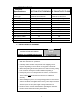
STEP 6:
With press standing upright and all bolts tightened install the worktable. Insert two table pins
in the two lowest holes. Take the worktable and tilt it at a sharp angle and insert it in the
uprights. (NOTE: The gussets welded to the table are at slight angles. The narrowest
dimension of these gussets go down. See drawing) (Step 1) Once worktable is in the
uprights turn it level and lower down and set it on the table pins. (Step 2) Take care when
doing this, a helper would be advised.
Gussets inside table
Step 1
Lower
Narrowest dimension
Step 2
STEP 7:
Locate the cylinder and remove the plastic protective cap on the end of the ram. (If
applicable) Carefully screw the cylinder from the top into the head traverse ram plate. Screw
this in as tight as possible while keeping the cylinders hydraulic hose fitting facing to the left.
(Cylinder may not be totally tight while keeping the fitting facing this way, but it will not effect
the presses operation.)
Using Teflon tape install the gauge to the
top of the cylinder facing forward.
Gauge
Hose fitting
STEP 8:
On the bench model hang the pumping unit in its holder bracket on the side of the frame.
Remove the plastic protective cap from the end of the hydraulic hose. Screw the hydraulic
hose onto the cylinder hose fitting. The fitting has a knurled collar that you can tighten by
hand. (Do not use a wrench because damage may occur to the fitting) The hose has a check
valve that prevents oil from escaping so if hose is ever removed air will not get in the system.
Install a nose piece and use table blocks when operating this machine.