
User Manual


Page 20
Com-Tech 200/400/800/1600 Power Amplifiers
damping factor is the value on the “Annealed Copper Wire”
line.
Note: Wire size increases as the AWG gets smaller
.
7. If the size of the cable exceeds what you want to use,
(1) find a way to use shorter cables, like using the
IQ System
,
(2) settle for a lower damping factor, or (3) use more than
one cable for each line. Options 1 and 2 will require the sub-
stitution of new values for cable length or damping factor in
the nomograph. For option 3, estimate the effective wire
gauge by subtracting 3 from the apparent wire gauge every
time the number of conductors of equal gauge is doubled.
So, if #10 wire is too large, two #13 wires can be substituted,
or four #16 wires can be used for the same effect.
SOLVING OUTPUT PROBLEMS
High-frequency oscillations can cause your amplifier
to prematurely activate its protection circuitry. The
effects of this problem are similar to the RF problems
described in Section 3.3.2. To prevent high-frequency
oscillations, follow these guidelines:
1. Bundle together each pair of loudspeaker conduc-
tors when using long cable runs or when different
amplifiers use a common cable tray or jacket. (Do
NOT bundle wires from different amplifiers.) This
reduces the chance of conductors acting like
antennas to transmit or receive the high frequen-
cies that can cause oscillation.
2. Avoid using shielded loudspeaker cable.
3. Never tie together input and output grounds.
4. Never tie together the output of different amplifiers.
5. Keep output cables separated from input cables.
6. Install a low-pass filter in series with each input
(see Section 3.3.2).
7. Install the input wiring according to the instructions
in Section 3.3.2.
Another problem to avoid is the presence of large sub-
sonic currents when primarily inductive loads are
used. Examples of inductive loads are 70 volt trans-
formers and electrostatic loudspeakers.
Inductive loads can appear as a short circuit at low fre-
quencies. This can cause the amplifier to produce
large low-frequency currents and activate its protec-
tion circuitry. Always take the precaution of installing a
high-pass filter in series with the amplifier’s input when
inductive loads are used. A three-pole, 18 dB per oc-
tave filter with a –3 dB frequency of 50 Hz is recom-
mended (some applications may benefit from an even
higher –3 dB frequency). Such a filter is described with
subsonic frequency problems in Section 3.3.2.
Another way to protect inductive loads from large low-
frequency currents and prevent the amplifier from pre-
maturely activating its protective systems is to parallel
a 590 to 708 µF nonpolarized motor start capacitor
and a 4 ohm, 20 watt resistor in series with the amplifier
output and the positive (+) transformer lead. This cir-
cuit is shown in Figure 3.14. It uses components that
are available from most electrical supply stores.
3. 3.4 Additional Load Protection
Com-Tech
amplifiers can generate enormous power
output. Using 8/4 ohm output, if your loudspeakers do
not have built-in protection from excessive power, it’s a
good idea to protect them. Loudspeakers are subject
to thermal damage from sustained overpowering and
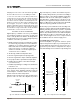
Fig. 3.15 Loudspeaker Fuse NomographFig. 3.14 Inductive Load (Transformer) Network
4 ohm, 20 watt
Resistor
590 to 708 µf Capacitor
120 VAC, N.P.
+
–
Inductive
Load
+
–
From
Amplifier
Output
1.0
1.2
1.4
1.6
2.5
3
4
5
6
7
8
9
10
12
14
16
20
25
30
20
15
10
8
6
5
4
3
2
1.5
1
.8
.6
.5
.4
.3
.2
.15
.1
.08
3000
2000
1500
1000
800
600
400
300
200
150
100
80
60
40
30
20
15
10
8
6
4
3
2
1.5
1
SPEAKER Z
(ohms)
FUSE
(amps)
SPEAKER RATING
PEAK MUSIC POWER
(watts)
(Typically 4 times the continuous average power)
Example: Z = 8 ohms.
Peak Power = 75 W
Answer: Fuse = 1.5 A
2
40