www.cornelius.com Installation Manual ICE/BEVERAGE DISPENSER Model: Enduro-200/250 IMPORTANT: TO THE INSTALLER. It is the responsibility of the Installer to ensure that the water supply to the dispensing equipment is provided with protection against backflow by an air gap as defined in ANSI/ASME A112.1.2-1979; or an approved vacuum breaker or other such method as proved effective by test.
TABLE OF CONTENTS Page SAFETY PRECAUTIONS . . . . . . . . . . . . . . . . . . . . . . . . . . . . . . . . . . . . . . . . . . . . . . . . . . . 1 DESCRIPTION . . . . . . . . . . . . . . . . . . . . . . . . . . . . . . . . . . . . . . . . . . . . . . . . . . . . . . . . 1 SPECIFICATIONS . . . . . . . . . . . . . . . . . . . . . . . . . . . . . . . . . . . . . . . . . . . . . . . . . . . . . 1 INSTALLATION INSTRUCTIONS . . . . . . . . . . . . . . . . . . . . . . . . . . . . . . . . . . . . . . . . . . .
SAFETY PRECAUTIONS Always: Disconnect power to the dispenser before servicing or cleaning. Never: Place hands inside of hopper or gate area without disconnecting power to the dispenser. Agitator rotation occurs automatically when dispenser is energized! This ice dispenser has been specifically designed to provide protection against personal injury and eliminates contamination of ice.
INSTALLATION INSTRUCTIONS 1. Locate the dispenser indoors on a level counter top. A. Note: LEG OPTION Before installing legs, the plastic plugs must be removed. Unpack the four (4) legs and install them into the threaded holes provided in the bottom of the unit. The installer must provide flexibility in the product and utility supply lines to permit shifting the position of the dispenser sufficiently to clean the area beneath it.
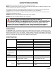
GATE RESTRICTOR PLATE ADJUSTMENT CAUTION: Disconnect power to dispenser before installing, removing or adjusting restrictor. The restrictor plate may be adjusted up or down as shown in Figure 2 to reduce or increase the ice dispensing rate, especially desirable when using glasses or other containers with small openings. Adjustment can be made by sliding the restrictor plate up or down with nuts loosened, to obtain the desired ice dispensing rate.
INSTALL PLATE ON STUDS AS SHOWN FIGURE 2. GATE RESTRICTOR PLATE 7/16 DIA. 30 1 13/16 26 7/16 1 5/16 12 9 18 5/8 21 1/4 30 11/16 29 3 1/2 9 3/16 Z Style 11 5/8 23 REMOVABLE SINK TO FRONT OF DRIP TRAY ON COUNTERTOP RECOMMENDED COUNTER OPENING SIZE 9 X 12 FOR UTILITIES AND BEVERAGE TUBING. OPENING CAN BE LOCATED ANYWHERE WITHIN SHADED AREA. TO FRONT TOP OF DRIP TRAY FIGURE 3.
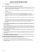
1 2 3 5 6 5 4 COLDPLATE INLET CONNECTIONS 3 2 1 FAUCETS COLD PLATE S6 S5 S4 S6 S5 S4 W4 W3 W2 W1 S3 S2 S1 S3 S2 S1 ITEMS INSIDE BROKEN LINE INCLUDED WITH UNIT 4 FAUCETS VIEWED FROM THIS SIDE FIGURE 4.
1 92181INS 2 3 4 FAUCETS VIEWED FROM THIS SIDE FIGURE 5.
1 2 3 7 4 FAUCETS VIEWED FROM THIS SIDE FIGURE 6.
1 92181INS 2 3 FAUCETS VIEWED FROM FRONT OF UNIT FIGURE 7. FLOW DIAGRAM (”B” UNIT WITH EIGHT BEVERAGE FAUCETS) 8 8 7 6 5 4 3 2 1 WATER MANIFOLD S8 S7 S6 S5 S4 S3 S2 S1 FAUCETS REMOTE REFRIGERATION SYSTEM ITEMS OUTSIDE BROKEN LINES ARE NOT INCLUDED WITH UNIT.
CAP WIRING DIAGRAM MOTOR HEATER AGITATOR MOTOR T’STAT BLK Q.C. CONNECTOR GRN R Y E E D L LIGHT 2 BLUE 1 ICE LEVEL SIGNAL OPTION N L SERVICE INFORMATION TO HINGE DANGER! DISPENSE SWITCH GATE SOLENOID (106VDC) TO 24V TRANSFORMER ELECTRIC SHOCK HAZARD. DISCONNECT POWER BEFORE SERVICING UNIT.
G L N TIMER L1 L2 RECTIFIER MOTOR HEATER AGITATOR MOTOR 3 N.O. O/L R C 2 S VEND SWITCH N.C. CAPACITOR MOTOR START RELAY GATE SOLENOID BALLAST LIGHT STARTER OPTIONAL BEVERAGE TRANSFORMER OPTIONAL FLAVOR VLVS OPTIONAL LOW ICE LEVEL LIGHT T’STAT VLV SOLENOIDS PCB BOARD KEYPAD OPTIONAL BEVERAGE VALVES OPTIONAL BEVERAGE VALVES BEVERAGE PANEL FIGURE 9.
WIRING DIAGRAM SERVICE INFORMATION (220–240 VAC) SHOCK HAZARD. DISCONNECT DANGER! ELECTRIC POWER BEFORE SERVICING UNIT. MOTOR HEATER AGITATOR MOTOR T’STAT TO HINGE GUSSET DISPENSE SWITCH GATE SOLENOID PCB BOARD BLK YEL BLU RED BRN WHT 2 3 KEYPAD ESD 4 (WATER–5) GRN/YEL LIGHT 2 BROWN BLUE FLAVOR SOLENOIDS E N L Q.C.
G L N EMI FILTER LINE FILTER TIMER L1 L2 RECTIFIER MOTOR HEATER POWER SWITCH AGITATOR MOTOR 3 N.O. O/L R C 2 S VEND SWITCH 4 START CAPACITOR N.C. MOTOR START RELAY GATE SOLENOID OPTIONAL BALLAST OPTIONAL LIGHT OPTIONAL STARTER OPTIONAL BEV. TRANSFORMER OPTIONAL BEV. TRANSFORMER OPTIONAL FLAVOR VLVS VLV SOLENOIDS BEV. FAUCETS BEVERAGE PANEL FIGURE 11.
TROUBLESHOOTING IMPORTANT: Only qualified personnel should service internal components or electrical wiring. WARNING: If repairs are to be made to a product system, remove quick disconnects from the applicable product tank, then relieve the system pressure before proceeding. If repairs are to be made to the CO2 system, stop dispensing, shut off the CO2 supply, then relieve the system pressure before proceeding.
Trouble Probable Cause BEVERAGE NOT SWEET ENOUGH. A. Empty syrup tank. B. Faucet brix requires adjusting. BEVERAGES NOT COLD (UNITS WITH BUILT-IN COLD PLATE). A. Unit standing with no ice in hopper or no ice in cold plate cabinet. FLAVOR SYRUPS DO NOT DISPENSE. A. No 24 volt power to PC board. B. No CO2 pressure. C.Empty syrup tank. D.Kinked tubing. E. Clogged inner nozzle. F. Defective PC board. G.Defective harness from keypad. H.Defective Flow control. I. Defective solenoid harness. J.
WARRANTY IMI Cornelius Inc. warrants that all equipment and parts are free from defects in material and workmanship under normal use and service. For a copy of the warranty applicable to your Cornelius product, in your country, please write, fax or telephone the IMI Cornelius office nearest you. Please provide the equipment model number and the date of purchase. IMI Cornelius Offices AUSTRALIA D P.O.