
User's Manual


3
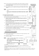
Step 3: The Door Contact has an Internal Magnetic Switch Position marked by a protrusion
on one side (refer to figure) of the Door Contact. Ensure the Internal Magnetic Switch
side is facing the magnet.
Step 4: Fit the magnet on the door using the small piece of double sided adhesive tape or
with provided screws. The magnet must align with the marked side of the door
contact.
<
<
N
N
O
O
T
T
E
E
>
>
The magnet should not be more than 15 mm from the detector when the door is
closed.
Windows can be protected similar to door installations. When fitting to a window
fix the magnet to the moving window part and the door switch to the stationary
frame.
U
U
s
s
i
i
n
n
g
g
t
t
h
h
e
e
E
E
x
x
t
t
e
e
n
n
s
s
i
i
o
o
n
n
T
T
e
e
r
r
m
m
i
i
n
n
a
a
l
l
.
.
The Door Contact has an Extension Terminal providing enhanced installation flexibility.
The Extension terminal may be useful for the following:
If the Door Contact cannot be mounted on the door frame, you can connect an
additional extension magnet switch to the Extension Terminal and mount the
Door Contact remotely.
More than one window and door can be protected by a Door Contact using the
additional magnet and extension magnet switch. The switches must be wired to
the Extension Terminal as shown:
Any dry contact device with N.C. (Normally Closed), such as a Broken Glass
detector, Smoke Sensor, Gas detector, Water Sensor etc, can be connected to
the Extension Terminal. Allowing the Door Contact to serve as an Universal
Transmitter.
The Extension Terminal forms a closed loop with the device connected to it. When the
Loop is opened (the device is triggered), the Door Contact is activated.
The device connected to the Extension Terminal is in series with the internal magnet
Switch. Meaning both can work together simultaneously.
You can choose to use the Extension Terminal and bypass the internal magnet switch or
to use both together.
C
C
O
O
N
N
N
N
E
E
C
C
T
T
I
I
N
N
G
G
T
T
H
H
E
E
E
E
X
X
T
T
E
E
N
N
S
S
I
I
O
O
N
N
T
T
E
E
R
R
M
M
I
I
N
N
A
A
L
L
:
:
Step 1: Detach the base and cover assembly.
Step 2: The rear of the Door Contact has an Extension Hole designed specifically to allow
external wiring connections.
Step 3: Connect the external device(s) to the Extension Terminal as
shown in the diagram.
<
<
N
N
O
O
T
T
E
E
>
>
If both the Internal Magnet Switch and Extension
Terminal operate together, then:
When the protected door is opened/closed or
the external
device is triggered, the Door Contact activates and transmits a
signal immediately .
However, the Door contact will only transmit a Door Closed
or Restored signal after both the door and
the external
device are restored for 3 sec.
FCC Statement
This device complies with Part 15 of the FCC Rules. Operation is subject to the following two conditions:
(1) This device may not cause harmful interference, and
(2) This device must accept any interference received, including interference that may cause undesired operation.
FCC Caution:
To assure continued compliance, any changes or modifications not expressly approved by the party responsible for compliance may
void the user's authority to operate this equipment. (Example - use only shielded interface cables when connecting to computer or
peripheral devices).