
Specifications


4
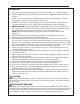
KNOW YOUR MACHINE DESCRIPTIONS
Operator Handle (1): Operator holds onto this handle to move the machine from one location to
another.
Solution Tank Lid (2): This lid screws off so the tank can be fi lled. The solution fi ll hose is
tethered to the lid, and hangs inside the arm of the Operator Handle.
Tools & Accessories (3): Various accessories can be stored on the machine.
Basket (4): This lift-off carrying basket sits on top of the round lid on the Recovery tank.
Recovery Hose (5): Waste water is picked-up through this hose.
Chemical Container Holders (6): Two molded-in bottle holders for chemical jugs.
Spray Hose (7): This hose delivers water from the machine to the cleaning tool.
Drain Hose (8): This hose is used to empty the recovery tank. NOTE: hold the end of the hose
above the water level in the tank to avoid sudden, uncontrolled fl ow of waste water when you
remove the cap, then lower the hose slowly to control the rate of discharge.
Quick Disconnect (9): Point of attachment for the Spray Hose (7).
Switch Plate (10): The machine’s on/off switches for the vacuum and for the pump are located
here and this is where the valve to change chemical feeds is located.
Castors and Wheels (11): Castors pivot for ease of steering, and large back wheels make it
easy to roll the machine from location to location.
Switch Plate (10): The machine’s on/off switches for the vacuum and for the pump are located
here and this is where the valve to change chemical feeds is located.
Power Cord (12): The 25 ft. power cord connects to a power cord pigtail on the rear of the
machine.
1
4
5
7
8
10
3
11
12
9
2
6