
Network Card User Manual


28
Catalyst 6500 Series DFC3A, DFC3B, and DFC3BXL Installation Note
78-15893-06
Installing the DFC3 Daughter Card
Installing the DFC3 Daughter Card on Modules Equipped with a Stiffener
Bracket
Note Some early versions of the WS-X6748-GE-TX Ethernet modules have a stiffener bracket mounted across
the top front part of the module, which requires a modified procedure to install the DFC daughter card.
Warning
During this procedure, wear grounding wrist straps to avoid ESD damage to the card. Do not directly
touch the backplane with your hand or any metal tool, or you could shock yourself.
Statement 94
To install the DFC daughter card on a WS-X6748-GE-TX Ethernet module that is equipped with a
stiffener bracket, follow these steps:
Step 1 Attach an ESD grounding strap to your wrist and to ground. (If you are unsure about the correct way to
attach an ESD grounding strap, refer to “Attaching Your ESD Grounding Strap” section on page 40 for
instructions.)
Step 2 Remove the new DFC3 daughter card from the antistatic bag and the installation hardware from the bag.
Note The DFC3 daughter card is designed to be installed on different modules; therefore, there may
be more mounting holes on the DFC3 daughter card than there are standoffs on the module. Not
all mounting holes on the DFC3 daughter card will be used in all installations. Visually verify
that there are standoffs beneath the mounting holes before installing the securing screws.
Step 3 Position the DFC3 daughter card over the module, and slightly tilt the DFC3 daughter card so that the
back end will clear the module connectors.
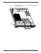
Step 4 Carefully slide the DFC3 under the two stiffener bracket tabs. (See Figure 20.) Verify that the DFC
daughter card is under the two stiffener bracket tabs.
Caution You must position the DFC daughter card under the two stiffener bracket tabs. If you install the DFC
daughter card above the two stiffener bracket tabs, you can permanently damage the DFC daughter card.
Step 5 Align the mounting holes on the DFC3 daughter card with the male standoffs on the module. (See
Figure 20.) Make sure that the remaining mounting holes on the DFC3 daughter card are aligned with
the remaining standoffs.
Note You should visually verify that there are standoffs beneath the mounting holes before installing
the securing screws.
Step 6 Press down on the edge of the DFC3 daughter card (see Figure 20) to seat the DFC3 daughter card power
connector to the module power connector.