
Installation manual for sliding gate operators


7
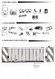
1. Ensure the operator is powered.
2. Position the brackets with magnets on the left and right ends of the rack where the end positions are assumed. The magnets are marked with L for left side
and R for right side and shall be positioned on the right or on the left from operator (see picture 12). The bracket positions can be adjusted by sliding the
bracket alongside the rack.
3. With the manually released operator move the gate in OPEN direction to reach the magnet xed on the racks. Ensure dimension between magnet and limit
switch are maintained (see picture 13).
4. When reached, section of the upper right digital segment on display will be on.
5. If needed, adjust the position of the magnet, verify that the upper right digital will be on and x the screws of the magnet bracket.
6. Repeat the same in CLOSE direction to reach the magnet xed at the Close position on the opposite side of the gate.
7. When reached, section of the lower right digital on display will be on.
8. If needed, adjust the position of the magnet, verify that the lower right digital will be on and x the screws of the magnet bracket.
9. Move the gate in in the middle position (between open and close limit).
The operator is ready for the Learning phase.
• The control board is already pre-installed and pre-wired to the motor terminal. No extra action is required.
To gain access to the control board remove the operator cover.The terminals for wiring accessories are directly accessible. To get access to the programming buttons
remove the transparent plastic cover and place it back once programming is nished.
5.7 Limit Switch Position Set Up
5.8 Access to the control Board and Motor connection
L R
12 - 20 mm
Picture 12 Picture 13
Picture 14
Congratulations! Herewith the mechanical installation of your
gate operator is nished. Please proceed with Programming
and Basic Settings to be able to start operation.
5. MECHANICAL INSTALLATION