The Chamberlain Group, Inc. 845 Larch Avenue Elmhurst, Illinois 60126-1196 www.liftmaster.com ® COMMERCIAL DOOR OPENER Model ATS 2113X 1/2 HP For Residential And Light Duty Commercial Use Install on Sectional Doors Only L O W H I G H L A NO R M H I G H L O W L A NO R M WN DORCE FO UP E RC FO Owner’s Manual ■ Please read this manual and the enclosed safety materials carefully! ■ Fasten the manual near the garage door after installation.
TABLE OF CONTENTS Introduction 2-5 Adjustment Safety symbol and signal word review........................2 Preparing your garage door ........................................3 Tools needed ...............................................................3 Planning .....................................................................4 Carton inventory ..........................................................5 Hardware inventory .....................................................
Preparing your garage door WARNING Before you begin: • Disable locks. • Remove any ropes connected to garage door. • Complete the following test to make sure your garage door is balanced and is not sticking or binding: 1. Lift the door about halfway as shown. Release the door. If balanced, it should stay in place, supported entirely by its springs. 2. Raise and lower the door to see if there is any binding or sticking.
Planning WARNING Identify the type and height of your garage door. Survey your garage area to see if any of the conditions below apply to your installation. Additional materials may be required. You may find it helpful to refer back to this page and the accompanying illustrations as you proceed with the installation of your opener. Without a properly working safety reversal system, persons (particularly small children) could be SERIOUSLY INJURED or KILLED by a closing garage door.
Carton Inventory purchased. If anything is missing, carefully check the packing material. Parts may be stuck in the foam. Hardware for installation is also listed below. Your garage door opener is packaged in two cartons which contain the motor unit and all parts illustrated below.
WARNING CAUTION ASSEMBLY STEP 1 Attach the Rail to the Motor Unit To avoid SERIOUS damage to opener, ONLY use bolts/fasteners mounted in top of motor unit. To avoid installation difficulties, do not run the garage door opener until instructed to do so. • Place the opener on packing material to protect the cover. • Remove the (2) 5/16"-18x1/2" washered bolts mounted in the top of the motor unit. • Position rail at a 45˚ angle to opener so one hole in rail and motor unit line up.
ASSEMBLY STEP 3 Outer Nut Tighten the Chain Lock Washer Inner Nut To Tighten Outer Nut • Spin the inner nut and lock washer down the threaded shaft, away from the trolley. • To tighten the chain, turn outer nut in the direction shown. As you turn the nut, keep the chain from twisting. • When the chain is approximately 1/2" (1.27 cm) above the base of the rail at its midpoint, re-tighten the inner nut to secure the adjustment. Sprocket noise can result if chain is either too loose or too tight.
INSTALLATION STEP 1 Determine the Header Bracket Location Unfinished Ceiling WARNING WARNING Header Wall To prevent possible SERIOUS INJURY or DEATH: • Header bracket MUST be RIGIDLY fastened to structural support on header wall or ceiling, otherwise garage door might not reverse when required. DO NOT install header bracket over drywall. • Concrete anchors MUST be used if mounting header bracket or 2x4 into masonry.
INSTALLATION STEP 2 Install the Header Bracket Wall Mounting Holes You can attach the header bracket either to the wall above the garage door, or to the ceiling. Follow the instructions which will work best for your particular requirements. Do not install the header bracket over drywall. If installing into masonry, use concrete anchors (not provided). CEILING MOUNT ONLY The nail hole is for positioning only. You must use lag screws to mount the header bracket.
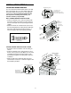
INSTALLATION STEP 3 Attach the Rail to the Header Bracket • Position the opener on the garage floor below the header bracket. Use packing material as a protective base. NOTE: If the door spring is in the way you’ll need help. Have someone hold the opener securely on a temporary support to allow the rail to clear the spring. • Position the chain pulley bracket against the header bracket. • Align the bracket holes and join with a clevis pin as shown. • Insert a ring fastener to secure.
WARNING CAUTION INSTALLATION STEP 4 Position the Opener To prevent damage to garage door, rest garage door opener rail on 2x4 placed on top section of door. SECTIONAL DOOR ONLY A 2x4 laid flat is convenient for setting an ideal door-to-rail distance. • Raise the opener onto a stepladder. You will need help at this point if the ladder is not tall enough. • Open the door all the way and place a 2x4 laid flat on the top section beneath the rail.
WARNING WARNING INSTALLATION CAUTION STEP 6 WARNING Install the Door Control To prevent possible SERIOUS INJURY or DEATH from electrocution: • Be sure power is not connected BEFORE installing door control. • Connect ONLY to 24 VOLT low voltage wires. To prevent possible SERIOUS INJURY or DEATH from a closing garage door: • Install door control within sight of garage door, out of reach of children at a minimum height of 5 feet (1.5 m), and away from all moving parts of door.
WARNING INSTALLATION STEP 7 CAUTION Install the Light To prevent possible OVERHEATING of the endpanel or light socket, • DO NOT use short neck or specialty light bulbs. • DO NOT use halogen bulbs. Use ONLY incandescent. • Install a 75 watt maximum light bulb in the socket. The light will turn ON and remain lit for approximately 4-1/2 minutes when power is connected. Then the light will turn OFF. • If the bulb burns out prematurely due to vibration, replace with a “Garage Door Opener” bulb.
INSTALLATION WARNING STEP 9 WARNING Electrical Requirements To prevent possible SERIOUS INJURY or DEATH from electrocution or fire: • Be sure power is not connected to the opener, and disconnect power to circuit BEFORE removing cover to establish permanent wiring connection. • Garage door installation and wiring MUST be in compliance with all local electrical and building codes. • NEVER use an extension cord, 2-wire adapter, or change plug in ANY way to make it fit outlet. Be sure the opener is grounded.
WARNING INSTALLATION STEP 10 Install The Protector System ® • Be sure power is not connected to the garage door opener BEFORE installing the safety reversing sensor. • To prevent SERIOUS INJURY or DEATH from a closing garage door: – Correctly connect and align the safety reversing sensor. This required safety device MUST NOT be disabled. – Install the safety reversing sensor so beam is NO HIGHER than 6" (15 cm) above garage floor.
INSTALLING THE BRACKETS Figure 1, 2 and 3 show recommended assembly of bracket(s) and “C” wrap based on the wall installation of the sensors on each side of the garage door as shown on page 15, or on the garage door tracks themselves. Figure 4 and 5 are variations which may fit your installation requirements better. Make sure the wraps and brackets are aligned so the sensors will face each other across the garage door.
MOUNTING AND WIRING THE SAFETY SENSORS • Center each sensor unit in a “C” wrap with lenses pointing toward each other across the door (see Figure 6). • Secure sensors with the hardware shown. Finger tighten the wing nut on the receiving eye to allow for final adjustment. Securely tighten the sending eye wing nut. • Run the wires from both sensors to the opener (see Figure 7). Use insulated staples to secure the wire to wall and ceiling. • Strip 1/4" (6 mm) of insulation from each set of wires.
WARNING CAUTION INSTALLATION STEP 11 Fasten the Door Bracket Fiberglass, aluminum or lightweight steel garage doors WILL REQUIRE reinforcement BEFORE installation of door bracket. Contact your door manufacturer for reinforcement kit. A horizontal brace should be long enough to be secured to 2 vertical supports. A vertical brace should cover the height of the top panel. The illustration shows one piece of angle iron as the horizontal brace.
INSTALLATION STEP 12 Inner Trolley Connect Door Arm to Trolley Outer Trolley SECTIONAL DOORS ONLY • Make sure garage door is fully closed. Pull the emergency release handle to disconnect the outer trolley from the inner trolley. Slide the outer trolley back (away from the door) about 2" (5 cm) as shown in Figures 1, 2 and 3. • Figure 1: – Fasten straight door arm section to outer trolley with the 5/16"x1" clevis pin. Secure the connection with a ring fastener.
WARNING ADJUSTMENT STEP 1 Adjust the UP and DOWN Travel Limits Without a properly installed safety reversal system, persons (particularly small children) could be SERIOUSLY INJURED or KILLED by a closing garage door. • Incorrect adjustment of garage door travel limits will interfere with proper operation of safety reversal system. • If one control (force or travel limits) is adjusted, the other control may also need adjustment. • After ANY adjustments are made, the safety reversal system MUST be tested.
WARNING ADJUSTMENT STEP 2 Adjust the Force Without a properly installed safety reversal system, persons (particularly small children) could be SERIOUSLY INJURED or KILLED by a closing garage door. • Too much force on garage door will interfere with proper operation of safety reversal system. • NEVER increase force beyond minimum amount required to close garage door. • NEVER use force adjustments to compensate for a binding or sticking garage door.
WARNING ADJUSTMENT STEP 3 Test the Safety Reversal System Without a properly installed safety reversal system, persons (particularly small children) could be SERIOUSLY INJURED or KILLED by a closing garage door. • Safety reversal system MUST be tested every month. • If one control (force or travel limits) is adjusted, the other control may also need adjustment. • After ANY adjustments are made, the safety reversal system MUST be tested. Door MUST reverse on contact with 1-1/2" (3.
WARNING OPERATION IMPORTANT SAFETY INSTRUCTIONS WARNING To reduce the risk of SEVERE INJURY or DEATH: 1. READ AND FOLLOW ALL WARNINGS AND INSTRUCTIONS. 2. ALWAYS keep remote controls out of reach of children. NEVER permit children to operate or play with garage door control push buttons or remote controls. 3. ONLY activate garage door when it can be seen clearly, it is properly adjusted, and there are no obstructions to door travel. 4. ALWAYS keep garage door in sight until completely closed.
Using the Wall-Mounted Door Control CARE OF YOUR OPENER LIMIT AND FORCE ADJUSTMENTS: Weather conditions may FORCE CONTROLS cause some minor changes in door operation requiring some re-adjustments, particularly during the first year of operation. Pages 20 and 21 refer to the LIMIT CONTROLS limit and force adjustments. Only a screwdriver is required. Follow the instructions carefully. Press the push button to open or close the door.
Having a Problem? 1. The opener doesn’t operate from either the Door Control or the remote control: • Does the opener have electric power? Plug a lamp into the outlet. If it doesn’t light, check the fuse box or the circuit breaker. (Some outlets are controlled by a wall switch.) • Have you disabled all door locks? Review installation instruction warnings on page 7. • Is there a build-up of ice or snow under the door? The door may be frozen to the ground. Remove any restriction.
PROGRAMMING NOTICE: If this Security✚® garage door opener is operated with a non-rolling code transmitter, the technical measure in the receiver of the garage door opener, which provides security against code-theft devices, will be circumvented. The owner of the copyright in the garage door opener does not authorize the purchaser or supplier of the non-rolling code transmitter to circumvent that technical measure.
To Add or Change a Keyless Entry PIN (Optional) NOTE: Your new Keyless Entry must be programmed to operate your garage door opener. USING THE “LEARN” BUTTON To change an existing, known PIN 1 2 3 9 1 7 1 If the existing PIN is known, it may be changed by one person without using a ladder. 1. Press the four buttons for the present PIN, then press and hold the # button. The opener light will blink twice. Release the # button. 2. Press the new 4-digit PIN you have chosen, then press ENTER.
WARNING WARNING Multi-Function Door Control (Optional) INSTALLATION Locate door control within sight of the door at a minimum height of 5 feet (1.5 m) where small children cannot reach, and away from moving parts of the door and door hardware. If installing into drywall, drill 5/32" holes and use anchors provided. For pre-wired installations (as in new home construction), it may be mounted to a single gang box.
REPAIR PARTS Rail Assembly Parts 3 1 4 2 KEY NO. 1 2 3 4 5 PART NO. DESCRIPTION 5 4A1008 41A2780 41A3489 CD1008 CD1010 CD1012 CD1014 83A11 6 41C771 Master link kit Chain pulley bracket Complete trolley assembly 8 Foot (2.44 m) Rail Assy. 10 Foot (3.05 m) Rail Assy. 12 Foot (3.66 m) Rail Assy. 14 Foot (4.27 m) Rail Assy. Rail grease NOT SHOWN Center Bracket (1 pc.) Installation Parts 3 4 2 1 NOT KEY NO.
Motor Unit Assembly Parts 1 2 3 4 15 18 7 18 17 15 (Down) Contact 8 9 16 5 12 14 LIMIT SWITCH ASSY. 6 10 13 Brown Wire Grey Wire DN UP Drive Gear Center Limit Contact KEY NO. PART NO. 1 2 3 41C5069 41B4569 41A5668 4 41A2817 5 6 7 8 9 143D100-1 175B88 30B532 12A461 41A3150 (Up) Contact 11 Yellow Wire DESCRIPTION Rail support bracket assembly kit Pulley (Chain) Gear and sprocket assembly.
ACCESSORIES 1702LM Outside Quick Release: Required for a garage with NO access door. Enables homeowner to open garage door manually from outside by disengaging trolley. 371LM SECURITY✚® 1-Button Remote Control: Includes visor clip. 59LM Outside Keylock: Opens the garage door automatically from outside when remote control is not handy. 372LM SECURITY✚® 2-Button Remote Control: NEMA 1 Push Button: Heavy Duty Door Control Push Button (one button). 373LM 8 Foot (2.
LIFTMASTER® SERVICE IS ON CALL HOW TO ORDER REPAIR PARTS OUR LARGE SERVICE ORGANIZATION SPANS AMERICA Selling prices will be furnished on request or parts will be shipped at prevailing prices and you will be billed accordingly. INSTALLATION AND SERVICE INFORMATION IS AS NEAR AS YOUR TELEPHONE SIX DAYS A WEEK. SIMPLY DIAL OUR TOLL FREE NUMBER: WHEN ORDERING REPAIR PARTS, ALWAYS GIVE THE FOLLOWING INFORMATION: • PART NUMBER • PART NAME 1-800-528-2817 HOURS: (Central Std. Time) 6:00 A.M. TO 7:00 P.M.