
MSDxx Manual v30


Cc-Smart Technology Co., Ltd
S: Saving All Parameter
L: Lock/Pause/Stoop the Motor immediately
U: Unlock Motor
r: Reset the Current Position to 0
R101: Reset the driver
C: Clear error list
G: Get moving information (G1: One Time; G3: Until Receive a New Data
With Frequency Respond 5Hz; G255: One time with Random Delay)
7. Protection & Indication Feature:
Protection:
Under/Over Voltage (vBus):
The motor driver output will be shut down when the power input voltage drops below the
lower limit. This is to make sure the MOSFETs have sufficient voltage to fully turn on and do not
overheat. ERR LED will blink during under voltage shutdown.
Temperature Protection:
The maximum current limiting threshold is determined by the board temperature. The higher
the board temperature, the lower the current limiting threshold. This way, the driver is able to
deliver its full potential depending on the actual condition without damaging the MOSFETs.
Overcurrent Protection with Active Current Limiting
When the motor is trying to draw more current than what the motor driver can supply, the
PWM to the motor will be chopped off and the motor current will be maintained at maximum
current limit. This prevents the motor driver from damage when the motor stalls or an
oversized motor is hooked up. OC LED will turn on when current limiting is in action.
8. Recommendation:
Wire Gauge
The smaller wire diameter (lower gauge), the higher impedance. Higher impedance wire
will broadcast more noise than lower impedance wire. Therefore, when selecting the wire
gauge, it is preferable to select lower gauge (i.e. larger diameter) wire. This
recommendation becomes more critical as the cable length increases. Use the following
table to select the appropriate wire size to use in your application.
Current (A) Minimum wire size (AWG)
10 #20
15 #18
20 #16
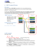
System Grounding
Good grounding practices help reduce the majority of noise present in a system. All