
Instruction Manual


IOM-PGR-1
6
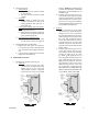
2. Place properly oriented seat (10) onto its
shoul der at the lower end of cage (4).
3. Place new o-ring lower stem seal (13) into
groove of valve plug (5).
4. Insert valve plug (5) upwards through lower
end of cage (4) and through the center hole
in guide bearing (9). Hold plug and cage
together in the closed position.
5. Place an oversized nut or stack of wash ers,
the same approximate height of the up per
diaphragm plate (7) and the lower diaphragm
plate (8), over the upper end of valve plug
(5) and temporarily secure with diaphragm
nut (11), manually tightened. Do NOT al low
valve plug to rotate against seat (10) during
tightening.
6. This completes ITA preliminary/partial reas-
sembly.
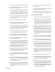
F. Main Valve Reassembly:
1. Place body (1) in a vise fl ange face up.
2. Reinstall internal sensing drilled plug (19) with
compatible thread sealant.
3. Insert the lower return spring (18) into the
body (1).
4. Fit the cage o-ring seal (14) into the body
groove.
5. With the ITA held manually in the closed po si-
tion, insert ITA into body (1).
6. Properly align bolt holes in the cage with
the holes in the body, as there is only one
circumferential location pos si ble for this align-
ment. Apply downward force to the top of the
cage (4) until the ITA is lowered suf fi cient ly
to engage the cage bolts (22) into the body
(1). Engage all of the cage bolts, Rotate the
cage bolts in one-half revolution increments
to pull down the ITA evenly, taking care NOT
TO “AN GLE” the ITA in the body. Torque the
cage bolts to 13-15 ft-lbs. (17.6-20.3 N-m).
7. Remove temporarily installed diaphragm nut
(11) and spacers of previous Step E.5. this
section.
8. Place new o-ring middle stem seal (13) into
groove of guide bearing (9) upper surface.
9. Position lower diaphragm plate (8) over up-
per end of plug (5) with tongue and groove
“groove” side up.
10. Place new o-ring upper stem seal (13) over
upper end of valve plug (5).
11. Place diaphragm (6) over end of valve plug
(5).
12. Place upper diaphragm plate (7) over upper
end of plug (5) with tongue and groove “ridge”
side down.
13. Place lubricant on valve plug (5) thread ed end.
Engage diaphragm nut (11) with upper end
of valve stem (5) as far as possible manually.
Place a wrench on diaphragm nut and a torque
wrench on the upper end of valve plug . Hold
torque wrench sta tion ary and rotate diaphragm
nut (7) to the following torque values:
DO NOT allow valve plug (20) to rotate
against seat ring (21) during tightening.
14. Aligning matchmarks and bolt holes, place
cover dome (2) onto body (1).
15. Reinstall all fl ange bolts (23) and nuts (24)
with nameplate (26) located under one bolt
head. Hand-tighten nuts. Make sure to install
the two longer bolts for the pilot bracket in the
correct location.
16. Evenly tighten the boltin in an alternating
cross pattern in one revolution increments to
the following torque values:
Body Size
in (DN)
Torque Value
Ft-lbs (N-m)
1/2" - 1" (15 - 25) 60 - 70 (81 - 95)
2" (50) 120 - 130 (163 - 176)
3" - 4" (80 - 100) 180 - 200 (244 - 271)
Body Size
in (Dn)
Torque Value
Ft-lbs (N-m)
1/2" - 2" (15 - 50) 30 - 35 (41 - 47)
3" - 4" (80 - 100) 45 - 50 (61 - 69)
G. Pilot Valve Disassembly:
WARNING
SYSTEM UNDER PRESSURE. Prior to per form ing any
maintenance, isolate the reg u la tor from the system and
relieve all pressure. Failure to do so could result in per-
sonal injury.