
Installation guide


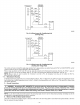


_AN COIL
_HE_MOS_A_ {CONTROL} HEAT PUMP
{CONTROL I
W2 _ W
_MERG_NCY HEAT REtAY
Fig. tS--Wiring Layout Neat Pump Unit
(Cooling and 2-Stage heat with 2 Outdoor Thermostats)
A94062
BRN
A94067
Fig. 1&--Transformer Connections
All unils have 3 motor speed taps. lx)w speed (red) is designed for mismatch outdoor unit applications Medium speed {blue) is designed for
straight matched operagons High s_eed (biack) is used with high external static duct s_tems of straight malcbed systems¸
PROCEDURE 5--REFRIGERANT TUBING CONNECTION AND EVACUATION
Use accessory tubing package o] field-supplied tubing of refrigerant grade Suction tube must be insulated. Do not use damaged, dirly, or
contaminated tubing because it may plug refrigerant grade Suction tub_ must be insulated Do not use damaged, dirty, or contaminated tubing
because it may plug refrigerant flow-control device ALWAYS evacuate the coil and fieid-suppbed tubing before opening outdoor unit service
Valves
Z_ CAUTION: A brazing shield MUST be used when tubing sets are being brazed to the unit connections to prevent
damage to the unit surface and condensate pan fitting caps. Failure to follow this CAUTION could result in minor personal
injury or product and property damage.
Units have sweat suction and bquid tube connections. Make suction tube connection first.
1. Cut tubing to correct lengg_.
2. Insert tube illtO sweat connection on unit until it bottoms
3. Braze connection using silvm bearing or non-silver beming brazing materials. Do not use solder (materials which melt below 800°F)
Consult local cede requirements
CAUTION: Wrap a wet cloth around rear of fitting to prevent damage to TXV and factory-made joints. Failure to follow
this CAUTION could result in minor personal injury or product and property damage.
4. Evacuate coil and tubing system 1o 500 microns using deep vacuum me,bed.