
Installation guide


t
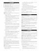
LEVEL (0")
TO
1/2"MAX
V2" MAX
UPFLOW OR DOWNFLOW HORIZONTAL
A02146
Fig. 14_Proper Condensate Drainage
When a fhmace is installed so that supply ducts can 7 air circulated
by the _hmace to areas outside the space containing the/hmace,
the return air shall also be handled by ducts sealed to furnace
casing. The ducts terminate outside the space containing the
ihrnace to ensure there will not be a negative pressure condition
within equipment room or space.
FIRE, INJURY OR DEATH HAZARD
Failure to ibllow this warning could result in fire, personal
injury, or death
Do not install fhrnace on its back. (See Fig. 15.) Safbty
control operation will be adversely affecte& Never connect
return-air ducts to hack of filrnace.
BACK
FRON]
A93043
Fig. 16--Prohibit Installation on Back
The thrnace and its return air system shall be designed and
installed so that negative pressure created by the air circulating fan
cannot affect another appliance's combustion air supply or act to
mix products of confbustion with circulating air, and that the air
circulating fhn of the fhmace, if installed in an enclosure commu-
nicating with another fllel-burning appliance not of the direct-vent
type, shall be operable only when any door or panel covering an
opening in the ihmace fan compartment or in a return air plenum
on dt/cts is in the closed position.
--€ [;NIT DAMAGE HAZARD
This gas fire, ace may be used %r construction heat provided
that:
-The [hrnace is permanently installed with all electrical
wiring, piping, venting and ducting installed according to
these installation instructions A return air duct is provide&
sealed to the ft_raace casing, and terminated outside the space
containing the thrnace This prevents a negative pressure
condition as created by the circulating air blower, causing a
flame rollout an&or drawing combustion products into the
strncttlre.
-The furnace is controlled by a thermostat It may not be "hot
wired" to provide heat continuously to the stlt/cture without
thermostatic control.
-(Dan outside air is provided for combustion. This is to
minimize the con'osive efDcts of adhesives, sealers and other
constn_ction materials. It also prevents the entraimnent of
d_wall dust into combustion air_ which can cause fouling and
plugging of Nrnace components.
-The temperature of the return air to the /hrnace is no less
than 55°F_ with no evening setback or shutdown. The use of
the fimaace while the structure is under construction is
deemed to be intermittent operation per our installation
instructions.
-The air temperature rise is within the rated rise range on the
furnace rating plate, and the firing rate has been set to the
nameplate value.
-The filters used to clean the circulating air during the
construction process nmst be either changed or thoroughly
cleaned prior to occupancy.
-The Nrnace, ductwork and filters are cleaned as necessary to
remove &ywall dust and construction debris fiom all HVA(
system components after construction is completed.
[;NIT DAMAGE HAZARD
Failure to fbllow this caution may result in minor property or
unit damage.
If these farnaces are installed in an unconditioned space
where ambient temperatt_res may be 32_F or lower, freeze
protection measures n-rest be taken (See Fig. 16)
14
32°F MINIMUM INSTALLED
AMBIENT OR FREEZE
PROTECTION REQUIRED
/
/
A93058
Fig. 16--Freeze Protection
Step 2--LowoHeat Only hstaltation
This 58MVP furnace can be installed to operate in the low-heat
only heating mode when sized using the low-heat heating capacity.
This is accomplished by placing setup switch SWI-2 in the ON
position to provide only low-heat operation. See Fig 32 and Table
9 With this semp_ high-heat operation will not occur