
Installation guide


58CV
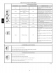
Table
12
—
Blower
Off
Delay
Setup
Switch
SETUP
SWITCH
DESIRED HEATING
MODE
(SW-7
AND
-8)
BLOWER
OFF
DELAY
(SEC.)
POSITION
Swi-7 swi-8
90
OFF OFF
120
ON
OFF
150
OFF
ON
180
ON ON
EXAMPLE
1:
0-2000
ft.
(0-610
M)
altitude
For
22,000
Btuh
per
burner
application
use
Table
14.
Heating
value
=
1000
Btuh/cu
ft.
Specific
gravity
=
0.62
Therefore:
Orifice
No. 43*
Manifold
pressure:
3.7-In.
W.C.
for
high-heat
1.6-In.
W.C.
for
low-heat
*
Furnace
is
shipped
with No.
43
orifices.
In
this
example
all
main
burner
orifices
are
the
correct
size
and
do
not
need
to
be
changed
to
obtain
proper
input
rate.
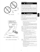
3.
Adjust
manifold
pressure
to
obtain
low
fire
input
rate.
(See
Fig.
49.)
a.
Turn
gas
valve
ON/OFF
switch
to
OFF.
b.
Remove
manifold
pressure
tap
plug
from
gas
valve.
c.
Connect
a
water
column
manometer
or
similar
device
to
manifold
pressure
tap.
d.
Turn
gas
valve
ON/OFF
switch
to
ON.
e.
Move
setup
SW1—2
on
furnace
control
to
ON
posi-
tion
to
lock
furnace
in
low-heat
operation.
(See
Table
10
and
Fig.
24.)
f.
Manually
close
blower
door
switch.
g.
Jumper
R
and
W/W1
thermostat
connections
on
con-
trol
to
start
furnace.
(See
Fig.
24.)
h.
Remove
regulator
adjustment
cap
from
low
heat
gas
valve
pressure
regulator
(See
Fig.
49.)
and
turn
low-
heat
adjusting
screw
(3/16
or
smaller
flat-tipped
screwdriver)
counterclockwise
(out)
to
decrease
input
rate
or
clockwise
(in)
to
increase
input
rate.
NOTE:
DO
NOT
set
low-heat
manifold
pressure
less
than
1.4-In.
W.C.
or
more
than
1.7-In.
W.C.
for
natural
gas.
If
manifold
pressure
is
outside
this
range,
change
main
burner
orifices.
i.
Install
low-heat
regulator
adjustment
cap.
j.
Move
setup
switch
SW1-2
to
off
position
after
com-
pleting
low-heat
adjustment.
k.
Leave
manometer
or
similar
device
connected
and
proceed
to
Step
4.
4,
Adjust
manifold
pressure
to
obtain high
fire
input
rate.
(See
Fig.
49.)
a.
Jumper
R
to
W/W1
and
W2
thermostat
connections
on
furnace
control.
This
keeps
furnace
locked
in
high-
heat
operation.
b.
Remove
regulator
adjustment
cap
from
high-heat
gas
valve
pressure
regulator
(See
Fig.
49)
and
turn
high
heat
adjusting
screw
(3/16-in.
or
smaller
flat-tipped
screwdriver)
counterclockwise
(out)
to
decrease
input
rate
or
clockwise
(in)
to
increase
input
rate.
NOTE:
DO
NOT
set
high-heat
manifold
pressure
less
than
3.2-In.
W.C.
or
more
than
3.8
In.
W.C.
for
natural
gas.
If
manifold
pressure
is
outside
this
range,
change
main
burner
orifices
to
obtain
manifold
pressure
in
this
range.
c.
When
correct
input
is
obtained,
replace
caps
that
con-
ceal
gas
valve
regulator
adjustment
screws.
Main
burner
flame
should
be
clear
blue,
almost
transparent
(See
Fig.
55.)
d.
Remove
jumpers
R
to
W/W1
and
R
to
W2.
5.
Verify
natural
gas
input
rate
by
clocking
meter.
NOTE:
Gas
valve
regulator
adjustment
caps
must
be
in
place
for
proper
input
to
be
clocked.
a.
Turn
off
all
other
gas
appliances
and
pilots
served
by
the
meter.
b.
Move
setup
switch
SW1-2
to
ON
position.
This
keeps
furnace
locked
in
low-heat
operation.
c.
Jumper
R
to
W/W1.
d.
Run
furnace
for
3
minutes
in
low-heat
operation.
e.
Measure
time
(in
sec)
for
gas
meter
to
complete
1
revolution
and
note
reading.
The
2
or
5
cubic
feet
dial
provides
a
more
accurate
measurement
of
gas
flow.
f.
Refer
to
Table
13
for
cubic
ft.
of
gas
per
hr.
g.
Multiply
gas
rate
cu
ft./hr
by
heating
value
(Btuh/cu
ft.)
to
obtain
input.
If
clocked
rate
does
not
match
re-
quired
input
from
Step
1,
increase
manifold
pressure
to
increase
input
or
decrease
manifold
pressure
to
de-
crease
input.
Repeat
steps
b
through
e
until
correct
low-heat
input
is
achieved.
Re-instail
low
heat
regu-
lator
seal
cap on
gas
valve.
h.
Move
setup
switch
SW1-2
to
OFF
position
and
jump-
er
R
to
W/W1,
and
W2.
This
keeps
furnace
locked
in
high-heat
operation.
Repeat
items
d
through
g
for
high-heat
operation.
6.
Set
Temperature
Rise
NOTE:
Blower
access
door
must
be
installed
when
taking
temperature
rise
reading.
Leaving
blower
access
door
off
will
result
in
incorrect
temperature
measurements.
FURNACE
DAMAGE
HAZARD
Failure
to
follow
this
caution
may
result
in
shorten
furnace
life.
Set
air
temperature
rise
within
limits
specified
on
the
rating
plate
to
prevent
reduced
life
of
furnace
components.
Operation
is
within
a
few
degrees
of
the
mid-point
of
rise
range
when
setup
switch
SW1-4
is
OFF.
UNIT
DAMAGE
HAZARD
Failure
to
follow
this
caution
may
result
in
overheating
the
heat
exchangers
or
condensing
flue
gases
in
heat
exchanger
areas
not
designed
for
condensate.
Temperature
rise
must
be
within
limits
specified
on
unit
rating
plate.
Operation
is
within
a
few
degrees
of
midpoint
of
rise
range
when
setup
switch
SW1-4
is
OFF.
When
setup
switch
SW1-4
is
ON,
operation
will
be
near
the
high
end
of
the
rise
range
for
improved
comfort.
Furnace
must
operate
within ranges
of
temperature
rise
specified
on
the
furnace
rating
plate.
Determine
air
temperature
rise
as
follows:
a.
Place
thermometers
in
return
and
supply
ducts
as
near
furnace
as
possible.
Be
sure
thermometers
do
not
see
heat
exchanger
so
that
radiant
heat
does
not
affect
readings.
This
practice
is
particularly
important
with
straight-run
ducts.