
Quick Start Guide


Network Video Recorder Quick Start Guide
9
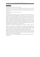
Figure 1. 3 Rear Panel for 4ch PoE NVR
Table 1. 3 Panel Description
1
Audio In
RCA connector for audio input.
2
Audio Out
RCA connector for audio output.
3
VGA Interface
DB9 connector for VGA output. Display local video output and menu.
4
HDMI
Interface
HDMI video output connector.
5
ALARM IN
Connector for alarm input.
ALARM OUT
Connector for alarm output.
6
LAN Network Interface
1 10/100/1000 Mbps self-adaptive Ethernet interface
7
USB Interface
Universal Serial Bus ports for additional devices such as USB mouse
and USB Hard Disk Drive (HDD).
8
Ground
Ground (needs to be connected when NVR starts up).
9
Power Supply
100 to 240 VAC for 8ch/16ch.
10
Power Switch
Switch for turning on/off the device.
11
Network Interfaces with
PoE function
Network interfaces for the cameras and to provide power over Ethernet.
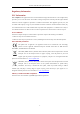
No.
Name
Description
1
Network Interfaces with
PoE function
Network interfaces for the cameras and to provide power over Ethernet.
2
Audio In
RCA connector for audio input.
3
Audio Out
RCA connector for audio output.
4
VGA Interface
DB9 connector for VGA output. Display local video output and menu.
5
HDMI
Interface
HDMI video output connector.
6
LAN Network Interface
1 10/100 Mbps self-adaptive Ethernet interface
7
USB Interface
Universal Serial Bus ports for additional devices such as USB mouse
and USB Hard Disk Drive (HDD).
9
Power Supply
48 VDC power supply.
10
Ground
Ground (needs to be connected when NVR starts up).