PIXMA iP6000D SERVICE MANUAL Canon Copyright 2004, Canon U.S.A. This technical publication is the proprietary and confidential information of Canon U.S.A. which shall be retained for reference purposes by Authorized Service Facilities of Canon U.S.A. Its unauthorized use is prohibited.
PIXMA iP6000D SERVICE MANUAL Revision 0 QY8-13A6-000 COPYRIGHT©2004 CANON INC. CANON PIXUS iP6100D/PIXMA iP6000 082004 XX 0.
Scope This manual has been issued by Canon Inc., to provide the service technicians of this product with the information necessary for qualified persons to learn technical theory, installation, maintenance, and repair of products. The manual covers information applicable in all regions where the product is sold. For this reason, it may contain information that is not applicable to your region.
I. MANUAL OUTLINE This manual consists of the following three parts to provide information necessary to service the PIXMA iP6000D: Part 1: Maintenance Information on maintenance and repair of the PIXMA iP6000D Part 2: Technical Reference New technology, technical information and FAQ's (Frequently Asked Questions), etc.
II. TABLE OF CONTENTS Part 1: MAINTENANCE 1. MAINTENANCE 1-1. Adjustment, Periodic Maintenance, Periodic Replacement Parts, and Replacement Consumables by Service Engineer 1-2. Customer Maintenance 1-3. Product Life 1-4. Special Tools 1-5. Serial Number Location 2. LIST OF ERROR DISPLAY / INDICATIONS 2-1. Operator Call Errors 2-2. Service Call Errors 2-3. Warnings 2-4. Troubleshooting by Symptom 3. REPAIR 3-1. Notes on Service Part Replacement (and Disassembling / Reassembling) 3-2.
4-12. Print Layout (Details) 4-13. Date Print Specifications 4-14. Photo Number Printing Specifications 5. FAQ (Problems Specific to the iP6000D and Corrective Actions) Part 3: APPENDIX 1. BLOCK DIAGRAM 2. CONNECTOR LOCATION AND PIN LAYOUT 2-1. Main Board 2-2. Print Beam Board 2-3. Card Slot Board 2-4. Operation Panel Board 2-5. Carriage Board (Print Head Connector) 3. PIXMA iP6000D SPECIFICATIONS 4.
Part 1 MAINTENANCE
1. MAINTENANCE 1-1. Adjustment, Periodic Maintenance, Periodic Replacement Parts, and Replacement Consumables by Service Engineer (1) Adjustment Adjustment Timing Purpose Tool Approx. time EEPROM initialization (EEPROM settings) At logic board ass'y replacement To initialize settings other than the following: - USB serial number - Destination setting - Waste ink counter - CD-R correction value None. 1 min.
1-3. Product Life (1) Printer Specified print volume (I) or the years of use (II), whichever comes first. (I) Print volume PIXMA iP6000D 5,000 pages Black 1,500 character pattern 1,500 pages Color A4, 7.5% duty per color pattern 1,300 pages A4, 30 % duty per color pattern 400 pages 4 x 6, 30 % duty per color pattern 1,000 pages Postcard, 30 % duty per color pattern 800 pages (II) Years of use 5 years of use (2) Print head Print volume: No.
2. LIST OF ERROR DISPLAY / INDICATIONS Errors and warnings are displayed by the following ways. 1) Errors are indicated by the number of times the LED blinks. 2) Errors and warnings are displayed on the LCD viewer on the operation panel. 3) Warnings are displayed on the printer driver's Status Monitor. 2-1. Operator Call Errors (by LED Blinking in Orange) LED blinking in orange 2 times 3 times Solution Error [Error code] No paper.
2-2.
2-4. Troubleshooting by Symptom Symptom Replace the - AC adapter, or - logic board ass'y*1. Strange noise. Remove foreign material, or attach a removed part if any. Printing stops mid-way. Replace the logic board ass'y*1. Multiple sheets feed. Replace the - sheet feed unit, or - cassette. Paper does not feed. Remove foreign material, or replace the - sheet feed unit, or - cassette. Paper feeds at an angle.
3. REPAIR 3-1. Notes on Service Part Replacement (and Disassembling / Reassembling) Service part Logic board ass'y QM2-1786 Notes on replacement*1 Adjustment / settings - Before removal of the logic board ass'y, remove the power cord, and allow for to sit approx. 1 minute (for discharge of capacitor's accumulated charges), to prevent damage to the logic board ass'y. - Before replacement, check the waste ink amount (by service test print or EEPROM information print).
3-2. Special Notes on Repair Servicing (1) Flexible cable and harness wiring, connection Exercise care when handling the flexible cables and harness wiring. Improper wiring or connection may cause a short-circuit, and may lead to ignition or emission of smoke.
(II) DCC holder unit wiring (III) Paper feed motor side wiring To the top
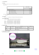
3-3. Adjustment / Settings (1) Paper feed motor adjustment Perform the following adjustments when the paper feed motor unit is replaced: 1) When attaching the motor, fasten the screws so that the belt is properly stretched (in the direction indicated by the blue arrow in the figure below). 2) After replacement, be sure to perform the service test print, and confirm that no strange noise or faulty print operation (due to dislocation of the belt or gear, or out-of-phase motor, etc.) occurs.
(3) Grease application 1 - 10
Part name Chassis Where to apply grease / oil Grease / oil name Grease / oil amount 1 Entire contact surface of the carriage slider rail FLOIL KG107A 3 drops 2 Cam contact portion FLOIL KG107A 1 drop 3 Carriage shaft sliding portion FLOIL KG107A 1 drop 4 Carriage shaft cam L sliding portion MOLYKOTE HP300 2 drops 5 Carriage shaft sliding portion FLOIL KG107A 1 drop 6 Carriage shaft sliding portion on the left side of the chassis FLOIL KG107A 1 drop 7 Carriage shaft cam L sliding
(4) Waste ink counter setting When the logic board ass'y is replaced, reset the waste ink counter. In addition, according to the waste ink amount, replace the waste ink absorber (the bottom case unit or the ink absorbers). The standard amount for waste ink absorber replacement is given in the table below. Waste ink amount*1 Bottom case unit or ink absorber replacement Less than 7% Not required. 7% or more Required. *1: Check the waste ink amount by service test print or EEPROM information print.
1) Turn on the printer. 2) Press and hold the Resume/Cancel button until the LED blinks the specified number of times listed in the table below, and release it. The operation starts. LED blinking Operation Remarks 1 time Print head manual cleaning 2 times Nozzle check pattern printing 3 times Paper feed roller cleaning 4 times Automatic print head alignment Set a sheet of plain paper (A4 or letter) in the sheet feeder.
1) With the printer power turned off, while pressing the Resume/Cancel button, press and hold the Power button. (DO NOT release the buttons. The LED lights in green to indicate that a function is selectable.) 2) While holding the Power button, release the Resume/Cancel button. (DO NOT release the Power button.) 3) While holding the Power button, press the Resume/Cancel button 2 times, and then release both the Power and Resume/Cancel buttons.
3-4. Verification Items (1) Service test print On the service test print (sample below), confirm the EEPROM information as shown below. (The information is given in the upper portion of the printout.) On the service test print (sample below), confirm the following items: - Check 1, nozzle check pattern: Ink shall be ejected from all nozzles - Check 2, top of form accuracy: The line shall not extend off the paper.
(2) EEPROM information print Print sample: 1:iPXXXXD 2:V1.00 3:IF(USB1=1) 4:D=004.
HDEEPROM 1:V0001 2:SN=0000-08D6 3:LN(15 15 15 15 63 63 15) 3: ID=00 4:IL=(BK=000 C=000 M=000 Y=000 PC=000 PM=000) Printed items: 1. Model name 2. ROM Version 3. Connected I/F (USB1) 4. Waste ink amount 5. Installation date 6. Operator call/service call error record 7. Last printing time 8. Purging count (manual/deep cleaning/timer/dot count/ink tank or print head replacement) 9. Cleaning time 10. Print head replacement count 11. Ink tank replacement count (BK/C/M/Y/PC/PM) 12. Ink status (BK/C/M/Y/PC/PM 13.
4. PRINTER TRANSPORTATION This section describes the procedures for transporting the printer for returning after repair, etc. 1) In the service mode, press the Power button to finish the mode, and confirm that the paper lifting plate of the sheet feeder unit is raised. 2) Keep the print head and ink tanks installed in the carriage. [See Caution 1 below.] 3) Turn off the printer to securely lock the carriage in the home position. (When the printer is turned off, the carriage is automatically locked in place.
Part 2 TECHNICAL REFERENCE
1. NEW TECHNOLOGIES (1) Multi-paper handling Paper feeding through the auto sheet feeder and the cassette, automatic duplex printing, and CD-R / DVD-R direct printing are available as standard features. - Sheet feeder: Supports name/credit card size and sticker sheets as well as conventional paper types and sizes. - Front cassette: Except name, credit card and legal size and sticker sheets, supports the same types and sizes of paper as the sheet feeder.
2. CLEANING MODE AND AMOUNT OF INK PURGED To prevent printing problems due to bubbles, dust, or ink clogging, print head cleaning is performed before the start of printing, except in the following cases: - Cleaning on arrival: Performed when the access cover is closed. - Cleaning by dot count: Performed after ejection of paper (or after printing on the back side of paper when auto duplex printing is performed). - Manual cleaning / deep cleaning: Performed manually.
3. PRINT MODE 3-1 Resolution by Print Mode during Printing via Computer Paper type Plain paper No. of passes Resolution (dpi) High Resolution Paper (HR-101N) Quality level 5 1 pass Bk: 300 x 300 Y, M, C: 300 x 300 Quality level 4 1 pass Bk: 300 x 300 Y, M, C: 300 x 300 No. of passes Resolution (dpi) Photo Paper Pro (PR-101/PH-101) No.
3-2 Resolution in Borderless Printing Paper type Plain paper Quality level 5 Quality level 4 No. of passes Quality level 3 Quality level 2 Quality level 1 8 passes 16 passes 2 passes Resolution (dpi) Bk, Y: 600 x 1200 M, C: 600x600 Photo Paper Pro No. of passes (PR-101/PH-101) Resolution (dpi) Glossy Paper No.
3-4 Resolution in Direct Printing Paper type Plain paper No. of passes Resolution (dpi) Photo Paper Pro No. of passes (PR-101/ SG-101/ KM-101/ MM-101) Resolution (dpi) Photo Paper Plus Glossy No. of passes (PP-101/ SG-101/ KM-101/ MM-101/ Resolution (dpi) GP-401/ EC-101/ KH-201N) Matte Photo Paper No.
4. PHOTO DIRECT PRINT FUNCTION 4-1 Host PC Memory Card Access Function with the Memory Card Startup Utility 4-1-1 Supported memory cards Media types compatible with the host computer memory card access function and Memory Card Direct Printing function are as follows: - Compact Flash Card (CF1, CF2 [micro drive]) (However, 5V is not supported.) - Smart Media Card (5V, 1M and 2M are not supported.
4-2 Memory Card Direct Printing Function 4-2-1 Print mode Displayed images print (Photo Gallery): Images in the memory card can easily be viewed on the LCD and printed, one by one. In the print confirmation screen, it is possible to specify the number of copies to print. Specify images (DPE Shop): Specifies the number of copies to print per image. It is not possible to specify the layout such that multiple images are included in one page.
- Data in digital camera is processed on PhotoShop6. When the original image file taken by the digital camera is processed on PhotoShop6, as PhotoShop6 leaves the thumbnail image in the original image file without deleting it, the following phenomena occur: ->Pre-processed data is displayed on the LCD for a moment. (In the LCD specifications, if the thumbnail image exists in the image file, the thumbnail image is displayed, and then full resolution image is displayed.
4-4 File Sort Full pathnames ("/DCIM/100CANON") are sorted in alphabetical order.
4-6-2 Media type Media types that can be printed in the Digital Camera Direct Printing are as follows: When the language setting on the digital camera is not set to Japanese. (Media types for overseas destinations are identical, however the panel display differs depending on the languages. The following is the display of US English.
4-7 PictBridge Function The following applies when the printer is connected to a PictBridge-supported digital camera. (As PictBridge is enabled when both the printer and digital camera have shared functionality, some functions may not be selectable, depending on the combination of the printer and digital camera.) For Bubble Jet Direct functionality, refer to 4.6 Bubble Jet Direct Function. For other companies' digital cameras, refer to the camera's manual.
4-8 Exclusive Processes 4-8-1 Exclusive processes in Memory Card Direct Printing and Digital Camera Direct Printing As it is impossible to simultaneously process Memory Card Direct Printing and Digital Camera Direct Printing, the following actions are taken: When the digital camera is connected via the digital camera connection cable: Memory Card Direct Printing settings and operation are not possible. Setting items are not displayed in the operation panel, and the print start button is invalid.
4-10 Card Slot-related Operations and Display 4-10-1 Timing and precautions when removing the memory card The following timing and precautions are suggested to protect the memory card data. - Remove the memory card while the Access lamp is not lit. (If the memory card is removed while the Access lamp is blinking or on, the data on the card is not assured.
4-11 DPOF Settings in the Memory Card Direct Printing Function 4-11-1 Supported DPOF functions DPOF Ver. 1.0 is supported. The following essential functions as a DPOF printer are supported. - Standard printing - No. of copies to be printed (1 page) - Image format (CIFF, EXIF (JPEG), JFIF) - Designation of images to be printed (relative path name) The following optional functions as a DPOF printer are supported. - Index printing - No.
- Index printing L: 15 photos, 2L: 35 photos, Post card: 24 photos, A4: 80 photos, LTR/A4: 80 photos, Name card/Card: 6 photos*2, Panorama: 30 photos) - Layout printing 2/4/8 photos with borderless/bordered (L, 2L, Post card, A4*1, Panorama, Name card/Card*2) Postcard (with ruled line) with borderless/bordered (L, 2L, Post card, A4*1, Panorama, Name card/Card*2) Album 4 photos with either side (L, 2L, Post card, A4*1, Panorama, Name card/Card*2) Mix three types (A4) - Photo Stickers*2 2/4/9/16 seals
4-12-4 Layout and image size Processing in borderless printing (including 2 photos / 4 photos / 8 photos / postcard with borderless) 1) Rotate the image data by 90 degrees (if necessary) to align the long edges of the image with those of the paper. 2) Enlarge (or reduce) the image data while maintaining the image's proportions so as to align either the long or short edges of the image with those of the paper , so that blank space in the paper is completely eliminated.
4-13 Date Print Specifications 4-13-1 Date print in Memory Card Direct Printing 1) Settings and data format Printing in DPOF (Index and Standard) mode: When date print is set to ON in the DPOF settings, the date is printed using the character strings in the DPOF settings, regardless of the date setting in the printer's operation panel.
4-14 Photo Number Printing Specifications 4-14-1 Photo number printing in Memory Card Direct Printing 1) Data format Printing in Index mode: Photo number (3-digit number) and DCF number (8-character number (***-****) displayed on the operation panel) are printed. (Printed without exception) Printed characters consist of 3 characters + space + 8 characters.
5. FAQ (Problems Specific to the iP6000D and Corrective Actions) No. * Function Phenomenon Margin (approx. 0.3mm) 1 C Print results Condition Cause - Paper feeding from the cassette, Photo Paper Plus Double Sided (A4), borderless printing, printing on the back side of paper Corrective action Possible call or complaint - In the printer driver, increase the amount of extension. - A margin appears on printouts. - Change the paper feeding method from the cassette to the auto sheet feeder.
cotton swab. If the phenomenon persists after conducting 1 and 2, servicing is required. Service: Wipe any soiling or dirt off from the sheet feed unit and the bottom case unit ribs*2. Scratches on paper 8 C - PP-101D, PP-101, PR101, SG-101, etc. - Paper feeding from the cassette Print results B Paper is curled Credit/name card sized paper can not be ejected.
6. PIXMA iP6000D Specifications Type Desktop serial color bubble jet printer Paper feeding method Auto sheet feed (sheet feeder, cassette, automatic duplex printing, CD-R printing*1) Resolution 4,800 dpi x 1,200 dpi (Max.) Throughput (Target value) Draft Standard BK (Fine Black) 11 ppm 4.3 ppm Color (Fine Color) 9 ppm 3.0 ppm Printing direction Bidirectional, uni-directional Print width Max. 203.2 mm (216 mm in borderless printing) Interface USB 2.
Direct memory card print function Operation panel 2.5 Color LCD, 19 keys File format JPEG (DCF, CIFF, Exif 2.2 or prior, JFIF), TIFF (Exif compliant), DPOF compliant Supported print paper [See 3-4.
4. Print Media Specifications (1) Plain paper / specialty paper The following types of paper are recommended: Type Name Plain paper (64 to 105 g/m2) Size Paper feeding method ASF stacking capacity (max.