
User Guide


CHAPTER 7 EXTERNALS/AUXILIARY MECHANISMS
COPYRIGHT
©
1999 CANON INC. CANON NP6512/6612/7120/7130/7130F REV.0 AUG. 1999 PRINTED IN JAPAN (IMPRIME AU JAPON)
7-3
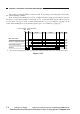
Figure 7-201
Power
plug
DS1
Composite power
supply circuit
Noise
filter
circuit
Door switch
Relay
RL601
FU102
Trans-
former
T600
Auxiliary
power
supply
circuit
+5V
Micro-
processor
(Q900)
Main
transformer
T101
Fixing
heater
control
circuit
DC
power
supply
circuit
Scanning
lamp
control
circuit
High-
voltage
power
supply
circuit
+24VR
+24VU
+5V
+24VU
+24VU
To ADF
Total copy counter
+24VU
Pre-exposure lamp
M1
Main motor/
main motor
driver PCB
Fixing heater
Primary charging
roller
Scanning lamp
Developing roller
Transfer roller
Static eliminator
+5V
+24VR
+24VU
+24VU
Control panel
AE sensor
+5V
Sensor
Solenoid
Scanner/lens
drive motor (M2)
Blanking lamp
+24VU
Scanner cooling fan
Toner level
detection
PCB
+24VU
DC
controller
PCB
II. POWER SUPPLY SYSTEM
A. Outline of the Power Supply System
Download Service Manual And Resetter Printer at http://printer1.blogspot.com