
User Guide


IV. INSTALLING THE
CONTROL CARD V
Caution:
Check to make sure that the MEMORY
TX/RX indicator is OFF before turning OFF
the main power switch.
1. Removing the Control Panel
1) Remove the following so that the inside cover
may be removed:
• Front door
• Fixing cover
• Drum unit (Release the developing assem-
bly.)
• Feeding assembly lever
• Registration roller knob
• Upper cassette
2) Remove the five screws, and remove the
inside cover.
3) Remove the following so that the control panel
may be removed:
• Fixing controller PCB (1 screw)
• Magnet plate from control panel top (1
screw)
• RS232C connector (1 screw)
4) Remove the four screws, and disconnect the
four connectors; then, remove the control
panel, and turn it over.
2. Before Installation the Control
Card
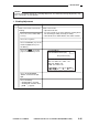
1) Remove the control card slot face plate q.
Figure 5-401
2) Remove the screw from the face plate w.
Figure 5-402
3) Remove the protection sheet from the display
of the Control Card V.
2
1
5–31
COPYRIGHT © 1996 CANON INC. CANON GP215/200 REV.0 JULY 1996 PRINTED IN JAPAN (IMPRIME AU JAPON)
5. INSTALLATION