
User Guide


D. Fans
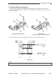
1. Removing the Fixing Heat Exhaust
Fan
1) Remove the four screws, and remove the rear
cover.
2) Remove the screw, and remove the left cover.
(Be sure to disengage the four hooks of the
left cover.)
3) Disconnect the two connectors q, remove the
two screws w, and disengage the three
hooks e to remove the fixing heat exhaust
fan.
Figure 4-213
2. Scanner Cooling Fan
1) Remove the four screws, and remove the rear
cover.
2) Disconnect the connector q, and remove the
tie-wrap; then, disengage the two hooks w
(left, right), and remove the scanner cooling
fan e.
Figure 4-214
3
2
1
3
13
1
3
2
4–7
COPYRIGHT © 1996 CANON INC. CANON GP215/200 REV.0 JULY 1996 PRINTED IN JAPAN (IMPRIME AU JAPON)
4. MECHANICAL SYSTEM