
Fax Machine User Manual


5-44
FAX-L1000 Chapter 5: Appendix
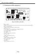
2.1.2 Explanation of LEDs and Switches
Figure 5-4 LEDs and Switches
LED1 to LED16
Monitors the state of the sensors and various status sent from the printer with the 16 LEDs.
LED17 (Communication)
Lights up when communicating with the printer.
LED18 (Sensor Test)
Used to adjust position of the envelope multiple feed sensor.
SW1 and SW2 (Operation Mode Select)
Set operation mode.
SW3 to SW9
Set various data sent to the printer.
SW10 (Laser ON)
Emits laser from the laser diode.
SW11 (Enter)
Enters the data set by SW3 to SW9.
SW12 to SW14 (Display Select)
Set display mode.
SW15 (Reset)
Resets the printer driver tester.
RY9-0124
CANON INC
MADE IN JAPAN
PRINTER DRIVER TESTER
JC1
SW15
1
0
Reset
J1
00
0
0
0
0
1
1
0
0
1
1
1
1
1
1
0
1
0
1
0
1
0
1
SW13
SW14
SW12
1
0
SW14 SW13 SW12
Display Select
00
0
0
0
0
1
1
0
0
1
1
1
1
1
1
0
1
0
1
0
1
0
1
SW4
SW5
SW3
Cassette Pick-up
Envelope Feeder Pick-up
Paper Feeder Pick-up
MP Tray Pick-up
Reserved
Cassette Pick-up
X1
1
1
0
0
SW7
1
0
1
0
SW6
All Black
All white
Horizontal lines
Vertical lines
1
0
0
0
1
1
0
0
1
0
0
0
SW5
SW6
SW4
1
0
1
0
SW3
Normal
F1
F5
F9
SW1SW2
1
0
SW1
0
1
0
SW2
1
0
0
SW3SW4SW5SW6SW7SW8SW9
1
0
1
0
1
0
1
0
1
0
1
0
1
0
RDYINHTest PrintScanner ONDPI600:0/1200:1
LED16 LED15 LED14 LED13 LED12 LED11 LED10 LED9 LED8 LED7 LED6 LED5 LED4 LED3 LED2 LED1
Cassette
210 Test
print
Cover
open
Full Delivery
2
Delivery
1
TOP PrefeedMP tray
Q2
C4
C3
SW11
SW10
LED17
Communication
1
0
1
0
Enter
Cassette Size
J2
LED18
Sensor Test
Analog Data
Reserved
Service Error
Operation Error
Jam
Option Sensor
Sensor/Switch
Reserved
Operation
Test Print
Density Ajust.
Operation Mode
Select
Laser ON