
Fax Machine User Manual


3-75
FAX-L1000 Chapter 3: Technical Reference
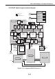
b) G3 reception
(1) The received image signal by L1, L2 is passed through a 2-line - 4-line conversion
circuit in the NCU board, and amplified.
The encoded data received by the MODEM IC (IC26) is read out by the CPU and then
it is written into the DRAM (IC3) reception buffer by the CPU.
(2) The main CPU (IC 17) software CODEC decodes the encoded data in the reception
buffer, deletes error lines, encodes to the non-compression function MR, and loads into
the DRAM. The main CPU counts the number of lines and calculates the length of one
page.
(3) The main CPU determines print functions such as direct print, linear reduction, and
page separation by following the length of one page, and sets a mode compatible with
the system controller and the CODEC IC.
(4) After the encoded image data recorded in the DRAM is transferred by high-speed DMA
transfer to the CODEC IC, it is serially forwarded to the system control IC (IC18).
(5) The system control IC converts the fax data resolution into a resolution suitable for print
data, and sends it to the ECNT board via the TWINS board.
(6) The ECNT board controls the main motor, laser, and high voltage for the received print
data, and prints out the data.
NOTE
When receiving, operations (1) and (2) above are repeated. When one page of
image data is loaded into memory, the recording tasks from (3) and on are
started as separate tasks.