
Fax Machine User Manual


3-25
FAX-L1000 Chapter 3: Technical Reference
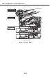
2.2.4 Electrical system layout
a) Board layout
a-1) SCNT board
The SCNT board, which contains the system controller which controls the entire fax, is
attached to the right side of the main unit.
a-2) NCU board
The NCU board, which controls the telephone line, is attached to the right side of the main
unit behind the SCNT board.
a-3) ECNT board
The ECNT board, which controls the printer assembly motor, solenoid, toner cartridge,
and fixing unit, is attached to the bottom of the main unit.
a-4) OPCNT board
The OPCNT board, which controls the operation panel, is attached to the inside of the
operation panel.
a-5) Power supply unit
The power supply unit, which controls the main unit’s power supply, is attached to the
right side of the main unit, to the right of the SCNT board.
a-6) Modular board
The Modular board, which is the telephone line and NCU board relay, is attached to the
right side of the main unit, in front of the SCNT board.
a-7) TWINS board
The TWINS board relays the SCNT board, Power supply unit, and ECNT board.
a-8) Paper size detection board 1 (Cassette 1)
The paper size detection board 1 is attached to the lower right side of the main unit.
a-9) Paper size detection board 2 (Cassette 2)
The paper size detection board 2 is attached to lower right side of the paper feed unit PF-
52.
a-10) Sensor board
The sensor board, is attached to the ADF assembly (Upper reader frame unit).