
Specifications


Copyright, 2004 Imaging Solutions Group of NY, Inc., All Rights Reserved
Revision 2.1 Subject to change without notice.
14 of 33
2.2 External Connectors
2.2.1 Firewire
TM
Connector: This interface is based on the industry standard 1394a
specification. Two connectors are provided to allow camera daisy chaining.
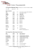
2.2.2 15-position D-SUB I/O Connector:
o Connector part number: Molex part number 83612-9020
o Thumb Screw part number: Molex MDSM – 9PE-Z10-VR25
o Recommended Cable: Molex CA 83422-9014
Pin Function Input/Output Type
1 Trigger + Optoisolated Input
2 Trigger - Optoisolated Input
3 GND
4 DC Input (Optional) Power Input
5 Strobe Open Collector Output
6 Programmable PWM Open Collector Output
7 GND
8 DC Input (Optional) Power Input
9 RS422 Trigger + Diff. TTL Input
10 RS422 Trigger - Diff. TTL Input
11 DC +5V Output Power Output
12 Programmable Output + Optoisolated Output
13 Programmable Output - Optoisolated Output
14 Reserved
15 GND
1
8
9
15
15-pin Micro-D EXT IO Connector, Front View