
User Guide


COPYRIGHT
©
1999 CANON INC. CANON CLC1120/1130/1150 REV.0 MAR. 1999 PRINTED IN JAPAN (IMPRIME AU JAPON)
2-29
CHAPTER 2 BASIC OPERATION
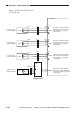
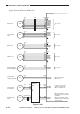
Inputs to the DC Driver PCB (12/13)
Figure 2-318
J671
J678
-3
-2
-1
J679
-3
-2
-1
J680
-3
-2
-1
J681
-3
-2
-1
-B9
-B10
-B11
-A1
-A2
-A3
-A4
-A5
-A6
J1021
-A7
-A8
-A9
TS1
TS2
TS3
TS4
BKTEP
J740
WTONER
PS68L
PS68S
-1
-2
-3
J742
+24Vf
TEMP
HUM
LHUM
GNDf
J743
-2
-1
J736
-2
-3
-4
-6
-1
-5
J1027
-A5
-A4
-A3
-A1
-A6
-A2
J1027
-B5
-B4
-B6
+5V
+5V
MTEP
CTEP
YTEP
+5V
+5V
+5V
M toner level
sensor
C toner level
sensor
Y toner level
sensor
Bk toner level
sensor
Waste toner full
sensor
Environment
sensor
DC driver PCB
When the toner inside the
M hopper is below a specific
level, '1'.
When the toner inside the
C hopper is below a specific
level, '1'.
When the toner inside the
Y hopper is below a specific
level, '1'.
When the toner inside the
Bk hopper is below a specific
level, '1'.
When the waste toner holds
toner in excess of a specific
level, '1'.
UN10