
User Guide


CHAPTER 2 BASIC OPERATION
2-28
COPYRIGHT
©
1999 CANON INC. CANON CLC1120/1130/1150 REV.0 MAR. 1999 PRINTED IN JAPAN (IMPRIME AU JAPON)
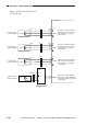
Inputs to the DC Driver PCB (11/13)
(CLC1150 only)
Figure 2-317
-B11
-B12
J1018
DVR5
+5V
DVR6
J620
J614
-B10
-1
-2
-3
-1
-2
-3
J611
J660
-B1
-B2
-B3
J1019
VR7
J640J625
-1
-2
-3
-A1
-A2
-A3
J345
J341
DVR4
-1
-2
-3
J607
J642
-B3
-B1
-B2
D1PLVR
D2PLVR
D2PWVR
MFPWVR
-B4
-B15
J1019
+5V
+5V
+5V
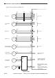
Cassette 1 paper
level detecting VR
Cassette 2 paper
width detecting VR
Cassette 2 paper
level detecting VR
Multifeeder paper
width detecting VR
DC driver PCB
Operates in conjunction with the
lifter shaft of the cassette 1, and
detects the level of copy paper.
(analog signal)
Operates in conjunction with the
side plate of the cassette 2, and
detects the level of copy paper.
(analog signal)
Operates in conjunction with the
lifter shaft of the cassette2, and
detects the level of copy paper.
(analog signal)
Operates in conjunction with the
side guide plate of the multifeeder,
and detects the width of copy paper.
(analog signal)
Pickup drive
PCB