
User Guide


CHAPTER 13 TROUBLESHOOTING
13-148
COPYRIGHT
©
1999 CANON INC. CANON CLC1120/1130/1150 REV.0 MAR. 1999 PRINTED IN JAPAN (IMPRIME AU JAPON)
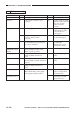
52 The cassette heater fails to operate.
Cause
Cassette heater
switch (SW8)
Environment
switch (SW6)
AC fuse PCB
Connector, wiring
Cassette heater
(H4, H5)
Thermal switch
(THS4, THS6)
SSR2 (100/120-V
model only)
DC driver PCB,
CPU PCB
Action
Turn it on.
End. (The heater will
remain powered at all
times.)
Replace the AC fuse
PCB.
Connect the connector
properly.
Replace the cassette
heater.
Replace SSR2.
Replace the DC driver
PCB or the CPU PCB.
Step
1
2
3
4
5
6
Yes/No
NO
YES
NO
NO
NO
NO
YES
Checks
Is the cassette heater switch on?
Turn off the environment switch. Is
the problem corrected?
Is there electrical continuity
between J14-1 and -3 of the AC
fuse PCB?
Are the connection and wiring
between the following connectors
normal?
J15, J16, cassette heater switch,
SSR2 (100/120-V model only),
environment switch
Turn off the power switch, and
disconnect the power plug; then,
remove the cassette heater that fails
to operate. Disconnect J52 (H4) or
J53 (H5) of the cassette heater.
Set the meter range to x1Ω, and
connect the meter probes to the
following terminals; does the index
of the meter swing?
Cassette Heater (H4)
J52-1 and -3
Cassette Heater (H5)
J53-1 and -3
Mount the cassette heater, and
connect the power plug. Set the
meter range to 12 VDC, and
measure the voltage between
J1025-1 (+; DRHOFF) and J1025-3
(-; GND) of the DC driver PCB. Is
it about 0 V?
Note: Step 6 applies to the 100/120-V model only.